


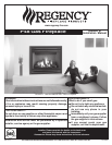

Regency P48 Zero Clearance Direct Vent Gas Fireplace
6
INSTALLATION
Diagram 1
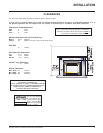
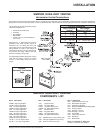
UNIT SPECIFICATIONS
This includes:
1) Clocking the appliance to ensure the correct
firing rate (rate noted on label 51,000 (NG)
Btu/h, 48,000 (LP) Btu/h) after burning ap-
pliance for 15 minutes.
2) If required, adjusting the primary air to en-
sure that the flame does not carbon. First
allow the unit to burn for 15-20 min. to
stabilize.
CAUTION: Any alteration to the product
that causes sooting or carboning that
results in damage is not the responsibil-
ity of the manufacturer.
MANUFACTURED
MOBILE HOME
ADDITIONAL
REQUIREMENTS
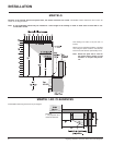
1) Ensure that structural members are not cut
or weakened during installation.
2) Ensure proper grounding using the #8
ground lug provided. See page 32.
LOCATING YOUR
GAS STOVE
1) When selecting a location for your stove,
ensure that the clearances outlined on this
page are met.
2) Provide adequate clearances for servic-
ing.
3) The appliance must be installed on a flat,
solid, continuous surface (e.g. wood, met-
al, concrete). This may be the floor, or
raised up on a platform to enhance its
visual impact. If the appliance is going to be
installed on carpeting, combustible linole-
um tile or other combustible material other
than wood flooring, the appliance must be
installed on a metal or wood panel extend-
ing the full width and depth of the appli-
ance.
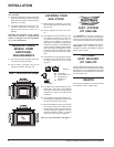
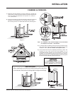
4) The P48 Direct Vent Gas Fireplace can be
installed in a recessed position or framed
out into the room as in A, B, C, D. See
Diagram 1.
HEARTH
A hearth is not mandatory, but is recommended
for aesthetics and for added safety.
5) This appliance is Listed for bedroom instal-
lations when used with a Listed Millivolt
Thermostat. Some areas may have further
requirements, check local codes before
installation.
6) The P48 Direct Vent Gas Fireplace is ap-
proved for alcove installations, which meet
the clearances listed on this page.
7) We recommend that you plan your installa-
tion on paper using exact measurements
for clearances and floor protection before
actually installing this appliance. Have an
authorized inspector, dealer, or installer
review your plans before installation.
Note: For vent terminations see page 11.
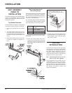
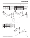
OPTIONAL
DUCT SYSTEM
KIT #946-556
The HeatWave Air Duct Kit increases the
effectiveness of your fireplace by dispersing
warm air from the fireplace to remote locations
in the same room or other rooms in your home.
Up to two kits may be installed on the fireplace.
Please Note: Only 1 HeatWave kit may be
operated at one time. This includes the internal
blower option as well.
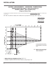
A) Flat on Wall
B) Flat on Wall Corner
C) Recessed into
Wall/Alcove
D) Corner
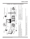
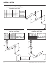
OPTIONAL
HEAT RELEASE
KIT #946-570
The Heat Release Kit expels warm air from the
fireplace to the outside of the building, allowing
the fireplace to be operated with less heat
entering the room. The kit may be used on either
the left or right side.