


Regency P48 Zero Clearance Direct Vent Gas Fireplace 21
INSTALLATION
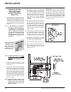
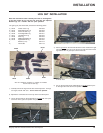
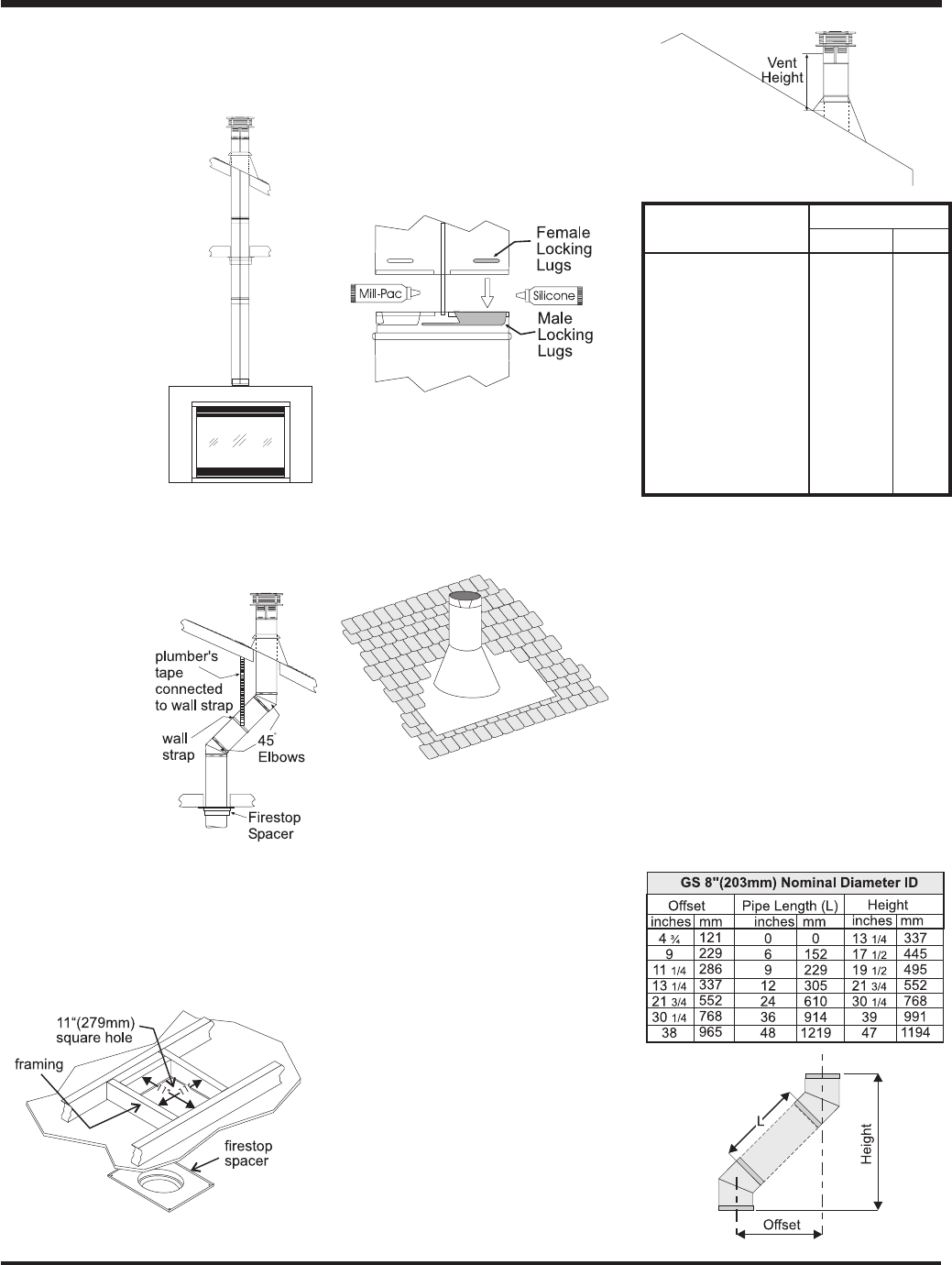
6) Continue to assemble pipe lengths.
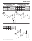
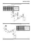
Note: If an offset is necessary in the attic
to avoid obstructions, it is impor-
tant to support the vent pipe every
3 feet (0.9 meter), to avoid exces-
sive stress on the elbows, and
possible separation. Wall straps
are available for this purpose
(Diagram 2).
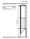
Galvanized pipe is desirable above the roof-
line due to its higher corrosion resistance.
Continue to add pipe sections through the
flashing until the height of the vent cap meets
the minimum height requirements specified in
Diagram 5 or local codes. Note that for steep
roof pitches, the vertical height must be in-
creased.
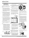
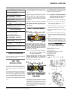
Diagram 3
Note:
Apply sealant "Mill-Pac" to inner pipe and
high temp silicone sealant to outer pipe
on every twist-lock joint.
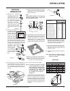
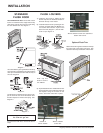
VERTICAL
TERMINATION
1) Maintain the 1-1/4"(32mm)
clearances (air spaces) to
combustibles when pass-
ing through ceilings, walls,
roofs, enclosures, attic raft-
er, or other nearby combusti-
ble surfaces. Do not pack air
spaces with insulation.
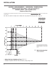
Check pages 16-17 for the
maximum vertical rise of the
venting system and the maxi-
mum horizontal offset limita-
tions.
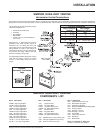
2) Set the gas appliance in its
desired location. Drop
a plumb bob down
from the ceiling to the
position of the appli-
ance flue exit, and
mark the location
where the vent will
penetrate the ceiling. Drill a small hole at his
point. Next, drop a plumb bob from the roof
to the hole previously drilled in the ceiling,
and mark the spot where the vent will
penetrate the roof. Determine if ceiling joists,
roof rafters or other framing will
obstruct the venting system. You
may wish to relo-
cate the appliance
or to offset, as
shown in Diagram
2 to avoid cutting
load bearing mem-
bers.
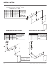
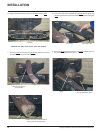
3) A Firestop spacer must be installed in the
floor or ceiling of every level. To install the
Firestop spacer in a flat ceiling or wall, cut
a 11 inch (279mm) square hole. Frame the
hole as shown in Diagram 3 and install the
firestop.
4) Assemble the desired lengths of pipe and
elbows. Ensure that all pipes and elbow
connections are in the fully twist-locked
position and sealed.
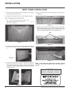
Diagram 4: The upper half of the flashing is
installed under the roofing material and not
nailed down until the chimney is installed.
This allows for small adjustments.
5) Cut a hole in the roof centered on the small
drilled hole placed in the roof in Step 2. The
hole should be of sufficient size to meet the
minimum requirements for clearance to
combustibles of 1-1/4"(32mm). Slip the
flashing under the shingles (shingles should
overlap half the flashing) as per Diagram 4.
Diagram 2
Offset Chart
A poor draft, or down drafting can result from
high wind conditions near big trees or adjoin-
ing roof lines, in these cases, increasing the
vent height may solve the problem.
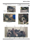
7) Ensure vent is vertical and secure the base
of the flashing to the roof with roofing rails,
slide storm collar over the pipe section and
seal with a mastic.
8) Install the vertical termination cap by twist-
locking it.
Note: Any closets or storage spaces,
which the vent passes through
must be enclosed.
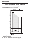
Diagram 5
Roof Pitch Minimum Vent Height
Feet Meters
flat to 7/12 2 0.61
over 7/12 to 8/12 2 0.61
over 8/12 to 9/12 2 0.61
over 9/12 to 10/12 2.5 0.76
over 10/12 to 11/12 3.25 0.99
over 11/12 to 12/12 4 1.22
over 12/12 to 14/12 5 1.52
over 14/12 to 16/12 6 1.83
over 16/12 to 18/12 7 2.13
over 18/12 to 20/12 7.5 2.29
over 20/12 to 21/12 8 2.44
Diagram 1