


Regency P42-3 Zero Clearance Direct Vent Gas Fireplace
8
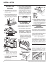
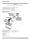
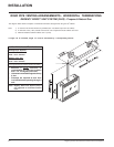
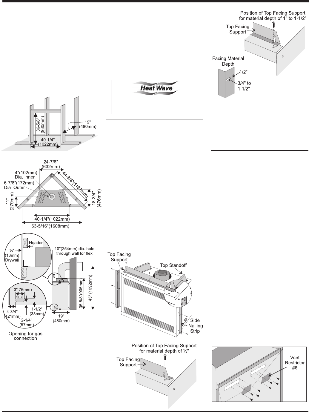
TOP ASSEMBLY &
NAILING STRIPS
The Top Facing Support and Side Nailing Strips
must be correctly positioned and attached be-
fore the unit is slipped into position.
1) The top standoffs are shipped installed.
2) The Top Facing Support and the 2 Side
Nailing Strips can be installed at different
depths depending on the width of your
facing. Match the depths of the top facing
support and the side nailing strips.
a) Mount Top Facing Support using the 3
supplied screws into the 3 pre-punched
screw holes on the top front of the unit.
See Diagrams 2 & 3 for the proper
position of the Top Facing Support for
the various material depths.
Diagram 1
Diagram 2
Diagram 3
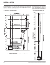
Diagram 4
INSTALLATION
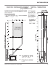
5) The unit does not have to be completely
enclosed in a chase. The clearance on top
of the unit from the top standoffs is 0" so
combustible building materials can be laid
directly on top of the standoffs. You must
maintain these clearances from the vent to
combustible materials: Flex Termination
clearance 1-1/2" (38mm), Simpson Dura-
Vent clearance or (1-1/4" (32mm). Combus-
tible materials can be laid against the side
and back standoffs and the stove base.
b) Mount the Side Nailing Strip using the 3
supplied screws into the 3 screw holes
or slots (diagram 4) on the side of the unit
and repeat for the other side. Use the hole
for a 1/2" (13mm) thick facing material and
the slot for a range of thickness from 1"
to 1-1/2" (25mm to 38mm).
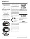
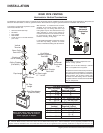
VENTING
INTRODUCTION
The P42 uses the "balanced flue" technology
Co Axial system. The inner liner vents products
of combustion to the outside while the outer
liner draws outside combustion air into the
combustion chamber thereby eliminating the
need to use heated room air for combustion and
losing warm room air up the chimney.
Note: These flue pipes must not be con-
nected to any other appliance.
The gas appliance and vent system must be
vented directly to the outside of the building, and
never be attached to a chimney serving a
separate solid fuel or gas burning appliance.
Each direct vent gas appliance must use it's
own separate vent system. Common vent sys-
tems are prohibited.
VENT RESTRICTOR
A vent restrictor may be required. Check the
diagrams on pages 13 to 18 to determine if the
#6 restrictor is needed for your vent configu-
ration. If required, attach the 2 piece #6 restric-
tor using 4 screws per piece to the inside top
of the firebox.
Note: 43" (1092mm) is the minimum
height for flex termination and
Simpson Dura-Vent terminations.
Diagram 1
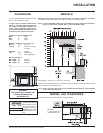
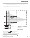
FRAMING AND
FINISHING
1) The facing allows for 1/2" (13mm) of dry-
wall material. The unit may be installed
directly on/or against standard combusti-
ble building materials.
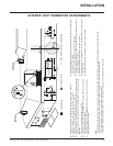
2) Frame in the enclosure for the unit with
framing material. The framed opening for
the assembled kit is 36-5/8" high x 40-1/4"
wide x 19" deep (930mm H x 1022mm W
x 483mm D). See Diagram 1.
3) For exterior walls, insulate the enclosure to
the same degree as the rest of the house,
apply vapour barrier and drywall, as per
local installation codes. (Do not insulate
the fireplace itself.)
4) The top louvers must not be closer than 36"
(914mm) to the ceiling.
The HeatWave Duct Kit has different
clearance and framing requirements,
check the HeatWave manual for details.