


8 FG37 Regency Rear Flued Room Sealed Freestanding Gas Heater
PLANNING YOUR FLUING INSTALLATION
INSTALLATION
FLUING
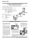
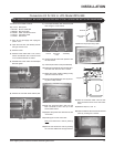
The Regency Room Sealed System (Horizontal
Termination Kit (946-110) and the Vertical Ter-
mination with the Co-linear Flex System in
combination with the REGENCY Room Sealed-
Rear Freestanding Gas Stoves (FG37-NG and
FG37-LPG) have been approved and listed as
Room Sealed heater systems by Australian
Gas Association.
The Horiz. Termination Kit (946-110) includes
everything required for a straight through the
wall installation, or add a 45
o
elbow for a corner
installation.
IMPORTANT
Read all instructions carefully before starting
the installation. Failure to follow these instruc-
tions may create a fire or other safety hazard,
and will void the warranty. Be sure to check the
fluing and clearance to combustible require-
ments on pages 6 to 9. Consult your local
building codes before beginning installation.
The location of the termination cap must con-
form to the requirements in the Exterior Flue
Terminal Locations diagram on page 7.
FLUING
INSTALLATION
PRECAUTIONS
The Regency Room Sealed System and the
Vertical Termination with the Co-linear Flex
System are engineered products that have
been designed and tested for use with the
FG37-NG, and FG37-LPG. The Regency war-
ranty will be voided and serious fire, health or
other safety hazards may result from any of the
following actions:
1) Installation of any damaged Room Sealed
component
2) Unauthorized modification of the Room
Sealed System
3) Installation of any component part not man-
ufactured or approved by Regency Indus-
tries Ltd.
4) Installation other than as instructed by Re-
gency Industries Ltd.
Warning: Always maintain required
clearances (air spaces) to nearby
combustibles to prevent a fire haz-
ard. Do not fill air spaces with insu-
lation.
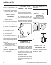
The minimum clearance requirements between
the outer wall of the flue pipe and nearby
combustible surfaces is 30mm. Be sure to
check the flue termination clearance require-
ments from decks, windows, soffits, gas reg-
ulators, air supply inlets and public walkways
as specified on page 7 and in your local building
codes.
The gas appliance and flue system
must be flued directly to the outside
of the building, and never be at-
tached to a chimney serving a sep-
arate solid fuel or gas-burning ap-
pliance.
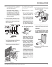
Each Room Sealed gas appliance must use its
own separate flue system. Common flue sys-
tems are prohibited.
SAFETY
PRECAUTIONS FOR
THE INSTALLER
1) Wear gloves and safety glasses for pro-
tection.
2) Exercise extreme caution when using lad-
ders or on roof tops.
3) Be aware of electrical wiring locations in
walls and ceilings.
See page 7 for Exterior Flue Termination
requirements.
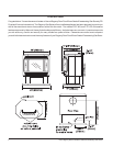
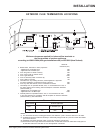
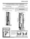
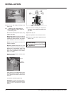
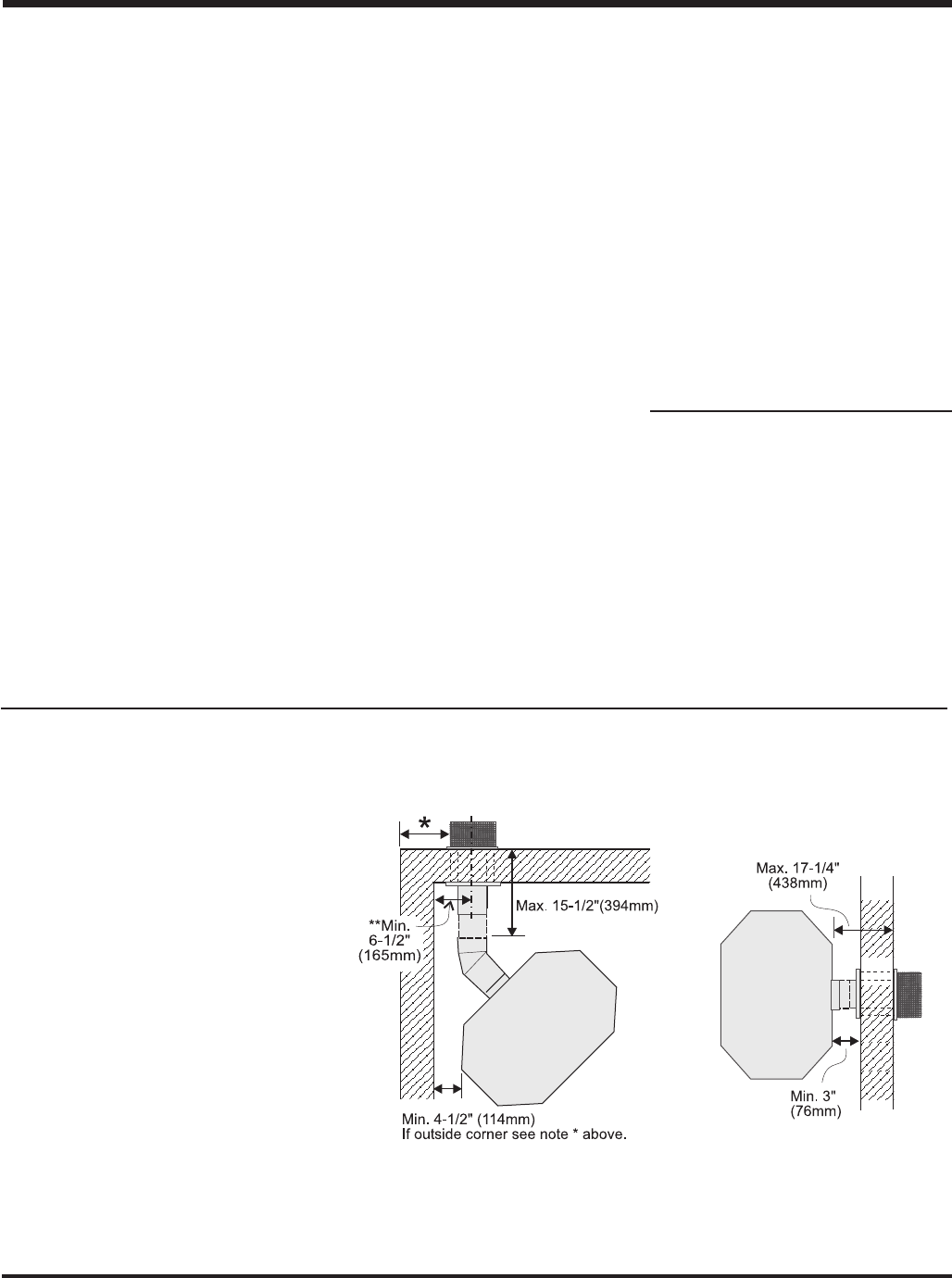
When planning your installation, it will be nec-
essary to select the proper length of flue pipe
for your particular requirements. Determine the
minimum clearance to combustibles from the
rear of the unit to the wall. It is also important to
note the wall thickness. Before cutting the flue
hole through the wall ensure that ALL flue and
termination clearances (see page 7) will be met.
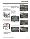
*If this is an outside corner, the minimum distance between the flue and the outside corner
is 12" (30cm). See "F" on the diagram on page 7.
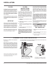
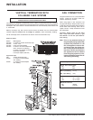
NOTE: Ensure compliance with the outside
flue terminal location before cutting hole as
both dimensions must be met.
For corner installation, Restrictor must
be set at 1-1/4" (32mm) open.
For straight rear installation, Restric-
tor must be set at 1-1/8" (29mm) open.