


11
U20/E21 Gas Insert Zero Clearance Kit
INSTALLATION
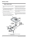
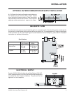
Diagram 410) Attach the brass trim to the faceplate by drilling a
1/8" (3mm) hole through the faceplate using the
hole in the trim as a guide. Fasten the trim to the
faceplate panels using the plated screws. #10
x1/2". See diagram 4 detail 'B'.
11) Attach the faceplate panels to the insert body
using the 4 remaining black screws. See diagram
4 detail 'A'. These screws will also fasten the
insert to the Zero Clearance sides.
12) Push the logo plate into the two holes in the
bottom left corner of the faceplate.
Note: This faceplate and Hearth Trim Assembly
replaces the standard Assembly as shown
in the U20/E21 Installation Manual.
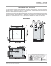
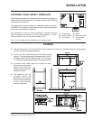
FINISHED FACING
NOTES
Install finished facing surface
of 1/2"(13mm) thickness on
framing. Drywall 1/2" (13 mm)
thick can extend flush with the
appliance on all three sides of
the front face. The height at
which the mantle must be
installed above the top louver
depends on the depth of the
mantle. If the mantle is to be
painted, use a heat resistant
paint to prevent discolouration.
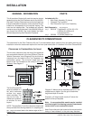
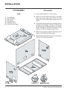
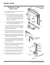
ZERO CLEARANCE TOP LOUVER
Attach the Top louver assembly to the Zero Clearance box by placing the
louver clamps into the square hole on the louver holding brackets.