


10
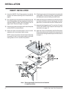
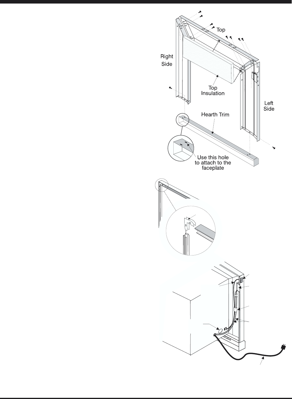
U20/E21 Gas Insert Zero Clearance Kit
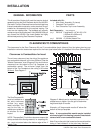
ON/OFF
Switch
Fan Speed
Switch
(Rear View)
Wires to
Fan Switch
Connectors
Self-adhesive
Wire Clip
For Gas
Connection
Wires to
On/Off
Switch
POWER CORD (3ft)
Diagram 3
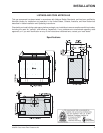
INSTALLATION
Faceplate Assembly
Diagram 1
Trim
Clips
Trim Assembly
Diagram 2
FACEPLATE & TRIM
INSTALLATION
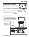
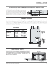
1) Lay the faceplate panels flat, facedown on something
soft so they don't scratch.
2) a) Take the top faceplate and align the holes in it
with the holes in the side panels. Using the
screws provided, attach from the top of the panel
(holes in the top panel are slightly larger than the
holes in the side panel to facilitate easier
installation). See diagram 1.
b) 4"(102mm) Hearth Trim. Attach the Hearth Trim
to the bottom of the faceplate side panels with
the screws provided. See diagram 1.
Hint: Don't tighten the screws down completely at
this point, do a trial fit to the unit. Make any
necessary adjustments and when it fits properly
then tighten down the screws.
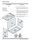
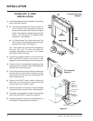
3) Using the trim clips provided, join the left side trim
(with the ON/OFF switch) to the top trim. See
diagram 2. Connect the right side trim to the top trim.
4) Place the trim on the assembled faceplate panels,
aligning the wire connections from the switches with
the notch on the left side panel.
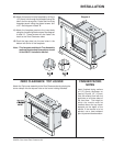
5) Connect the fan switch wires by taking the black and
red wires with the male ends (in the grey harness)
and connect them with the 2 wire connectors from
the fan speed control.
6) Connect the ON/OFF switch wires by taking the
black and red wires with the female ends and
connect them to the ON/OFF switch.
7) Install these wires in the clips on the left faceplate
to ensure they don't touch the insert. See diagram 3.
8) The power cord should be run behind the faceplate
panel from the U20/E21 to electrical outlet box.
9) Place top insulation in behind the top faceplate as in
the diagram. Pressed securely into place.