To Change Batteries
1. Remove cover on backside of the remote control. Install 3 AAA as
shown on the cover and then re-attach the cover.
2. Once OPERATION steps 1 to 3 are completed, the receiver/valve
and remote control are ready. Press any button on the remote
control to initiate the recognition process between the receiver/valve
and the remote control.
3. You may now use the functions as described in the REMOTE
CONTROL section.
Fig 8. Comfort control wiring diagram
Part 5 Troubleshooting
Refer to Fig 6
1. Locate the LED light on the gas valve.
2. LED will blink after every valid command received from the remote
control; this is not an error.
3. Failure codes may occur anytime after the pilot burner is lit.
4. The sequence is: failure code followed by light not blinking for 30
seconds.
5. In the event of multiple failure codes, the next failure code follows
previous failure code by approximately 3 seconds.
If an error code 3 is observed while performing the testing, complete the
following:
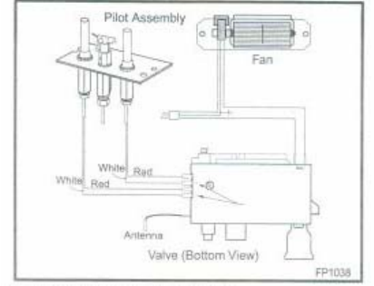
1. Make sure all the spade connectors are pushed all the way onto the
terminals. If error code 3 still shows, go onto the next step.
2. Switch the two front thermopile leads with the back two. Be sure the
white lead is connected to the spade marked with the white dot. If error
code 3 still shows, replace the thermopiles.
Page 18 of 27


