


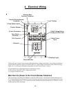

2. Mounting the Equipment
Aqua Logic Control Center
The Aqua Logic is contained in a raintight enclosure that is suitable for outdoor mounting. The control must
be mounted a minimum of 5 ft. (2 meters) horizontal distance from the pool/spa (or more, if local codes
require).
The Control Center is designed to mount vertically on a flat surface with the knockouts facing downward.
Because the enclosure also acts as a heat sink (disperses heat from inside the box), it is important not to
block the four sides of the control. Do not mount the Aqua Logic inside a panel or tightly enclosed area.
When selecting a location, note that the standard cables supplied with the Turbo Cell, flow switch, tem-
perature sensors, and valve actuators (if applicable) are all 12 ft. (365cm) long. Call the Goldline Service
Dept. (888-921-7665) for information regarding longer cables.
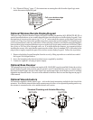
Temperature Sensors
The water temperature sensor is required for proper operation of the heater control and/or solar control
functions. This sensor is used to measure the pool water temperature when the pool/spa suction valve is
switched to the “pool” position and measures the spa water temperature when the valve is switched to the
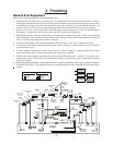
“spa” position. The sensor should be installed in the filtration plumbing after the filter but before either the
solar or conventionally fueled heaters—refer to the plumbing overview diagram.
1. Drill a 3/8” (10mm) diameter hole in the PVC piping and remove all chips and burrs.
2. Insert sensor until O-ring collar sits flush on the hole.
3. Position hose clamp over the sensor and gently tighten until O-ring makes an adequate seal. Do not
overtighten.
4. For maximum temperature accuracy, cover the sensor and 3” (6cm) of pipe on either side with
insulation and paint white.
Also, if the freeze protection option is selected for the filter pump or any aux output, the air sensor is used
to detect freeze conditions.
!
IMPORTANT: Mount the air sensor out of direct sunlight.
The solar sensor (order separately) is required only for the solar control function. Mount the sensor near
the solar collector array so that it is exposed to the same sunlight as the collectors. Use additional cable
(20 AWG) if necessary.
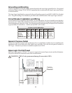
Optional Wired Remote Display/Keypad
The Aqua Logic Wired Remote Display/Keypad (Goldline part number AQL-REMOTE-PS-x) must be
mounted indoors or in a weather protected area (rain should never hit the display/keypad). Note that the
number of outputs on the remote (eg “4” or “8”) must match the outputs on the Aqua Logic main control
unit. Up to 3 remote display/keypads can be installed. The display/keypad is designed to mount onto a
standard electrical utility box (same box as a triple light switch, ideal for new construction) or can be
mounted directly onto any wall surface. When selecting a location, note that the wire to the Aqua Logic
main unit must be less than 500’ long. Follow the steps below:
1. Remove the display/keypad baseplate from the cover by lifting up on the cover at the lower end of
the keypad. See diagram on page 7.
2. Screw the baseplate in the desired position (screws supplied by installer).
6