


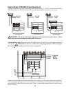
3. See “Electrical Wiring” (page 17) for instructions on running the cable from the Aqua Logic main
unit to the remote display/keypad.
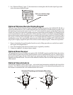
Optional Wireless Remote Display/Keypad
The Aqua Logic Wireless Remote Display/Keypad (Goldline part number AQL-REMOTE-RF-PS-x)
must be mounted indoors or in a weather protected area (rain should never hit the display/keypad). Note
that number of outputs on the remote (eg “4” or “8”) must match the outputs on the Aqua Logic main
control unit. There is no limit on the number of wireless remotes that can be installed. The display/keypad
can be mounted directly onto any wall surface. When selecting a location, note that the maximum distance
between the wireless remote and the base receiver on the Aqua Logic main control unit is 600 feet (200m)
line of site or 200 feet (65m) through walls, etc. If in doubt about the distance, test operation before
installing the remote. Also, note that the remote must be within 6 feet of a standard 120V wall outlet for the
plug-in power supply (supplied as part of the wireless remote display/keypad). Follow the steps below:
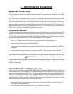
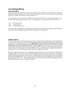
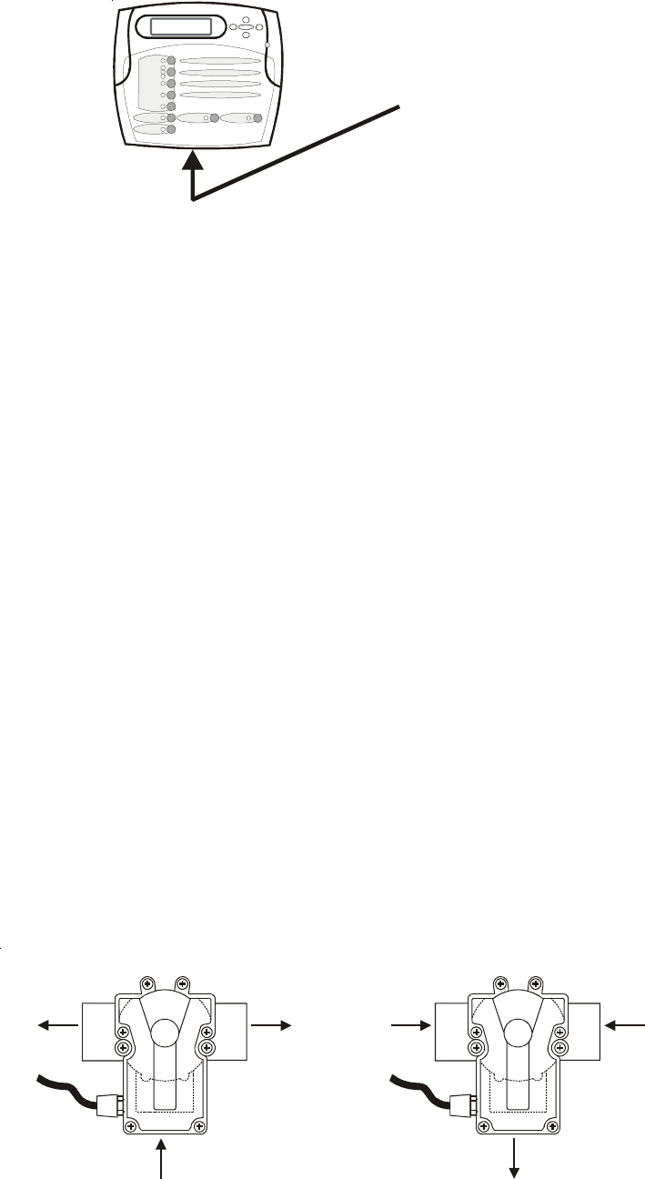
1. Remove the display/keypad baseplate from the cover by lifting up on the cover at the lower end of
the keypad. See diagram above.
2. Screw the baseplate in the desired position (screws supplied by installer).
3. Connect to supplied 9 volt plug-in power supply.
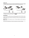
Optional Base Receiver
The optional base receiver (Goldline part number AQL-BASE-RF) must be installed if either the wireless
remote display/keypad or the wireless spaside remote is used. To install the base receiver, simply remove
the knockout on the upper left side of the Aqua Logic main control unit, insert the base receiver, and then
tighten the nut from the inside. Also refer to the manual for the Base Receiver and the diagram on page 18
of this manual.
Optional Valve Actuators
For actuators supplied with the Aqua Logic—refer to the Jandy instructions included in the kit with the
actuators. Note that the internal cams in the actuator may also have to be adjusted depending on the way
the actuator is mounted on the valve and the desired valve action.
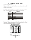
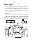
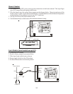
Standard Plumbing and Actuator Mounting
7
OUT
IN
OUT
IN
IN
OUT
(Common) (Common)
RETURN SUCTIO
N
Pull up on bottom edge
to remove cover