


Plumbing Requirements
The only special plumbing requirements for the Aqua Logic are the Turbo Cell and flow switch which are
typically plumbed after the heater but before the pool/spa return valve. Refer to page 9 for detailed
instructions.
Electrical Requirements
Power must be shut off at the circuit breaker before performing any wiring. Be sure to follow all local and
NEC electrical codes.
The Aqua Logic is designed to be used as a circuit breaker subpanel for all the pool equipment. Run the
electrical service from the house’s main panel to the Aqua Logic, then install the appropriate circuit breakers
and wire the pool equipment through the Aqua Logic relays. If desired, an external subpanel can be used.
The Aqua Logic control circuit requires 120VAC power. A utility receptacle (not included) can be mounted
in the side of the Aqua Logic box to provide 120VAC power if desired.
Installation Steps
Details on each installation step are presented on the following pages:
1. Prepare the pool water (page 3)
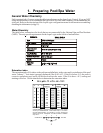
General Water Chemistry
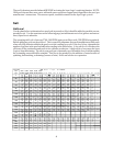
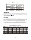
Salt
2. Mounting the equipment (page 6)
Aqua Logic main unit
Remote display/keypad (optional)
Temperature sensors
Valve actuators (if applicable)
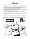
3. Plumbing (page 8)
General Pool Equipment
Turbo Cell
Flow Switch
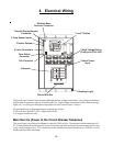
4. Electrical Wiring (page 10)
Main service
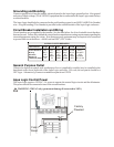
Grounding and bonding
Circuit breakers
Aqua Logic control power
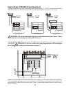
High Voltage pool equipment
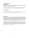
Low voltage wiring (temperature sensors, flow switch, etc.)
5. Aqua Logic control configuration (program desired control operation) (page 19)
6. System Startup and checkout (page 26)
2