


9
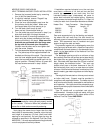
Gas vents supported only by the flashing and extend-
ing above the roof more than five feet should be
securely guyed or braced to withstand snow and wind
loads. We recommend use of insulated vent pipe
spacer through the roofs and walls.
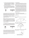
For protection against rain or blockage by snow, the
vent pipe must terminate with a listed vent cap which
complies with the local codes or, in the absence of such
codes, to the latest edition of the National Fuel Gas
Code, ANSI Z223.1.
The discharge opening must be a minimum of two
feet vertically from the roof surface and at least two(2)
feet higher than any part of the building within ten (10)
feet. Vent stack shall be at least five (5) feet in vertical
height above the drafthood outlet. The vent cap
location shall have a minimum clearance of four (4)
feet horizontally from, and in no case above or below,
unless a 4-foot horizontal distance is maintained, from
electric meters, gas meters regulators and relief equip-
ment.
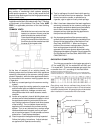
The weight of the vent stack or chimney must not rest
on boiler draft hood. Support must be provided in
compliance with applicable codes. The heater top and
draft hood must be readily removable for maintenance
and inspection. Vent pipe should be adequately sup-
ported to maintain proper clearances from combustible
construction.
Type "B" double wall or equivalent vent pipe is
recommended. However single wall metal vent pipe
may be used as specified in the latest edition of the
National Flue Gas Code ANSI Z223.1.
Fig. #8119.2
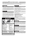
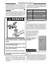
WARNING: Indoor heater require a drafthood that
must be connected to a vent pipe and properly vented
to the outside. Failure to follow this procedure can
cause fire or fatal carbon monoxide poisoning.
Vent piping the same size or larger than the draft
hood outlet is recommended, however, when the total
vent height is at least ten (10) feet (draft hood relief
opening to vent terminal), the vent pipe size may be
reduced as specified in the National Fuel Gas Code,
ANSI Z 223.1. As much as possible avoid long horizontal
runs of vent pipe and too many elbows.
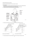
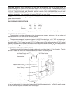
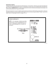
MODELS 330/331 AND 400/401
VENT TERMINAL/INDOOR STACK INSTALLATION
1. Remove the louvered jacket top by removing
four (4) #10 flat head screws.
2. If originally installed, remove "Pagoda" top
from the louvered jacket top.
3. Place the inner stack adapter panel over the
flue collector inside the heater. Make sure
the flanged side of the flue opening is up.
4. Turn the stack (draft hood) up side
down and set it down bottom side up.
5. Turn the jacket top panel (removed in step 1) up
side down and place it through the stack.
6. Attach the three (3) mounting brackets to the
stack using the screws provided and the holes
that are pre-drilled in the stack. Make sure the
brackets are positioned with the flange near
the top side of the stack (see illustration).
Caution must be taken not to over tighten and
strip the screw threads.
7. Turn the assembled stack and jacket top, right side
up. The jacket top will be trapped between the
brackets and the top of the stack. Place the stack
over the inner adapter panel flanged hole and
lower the louvered jacket top panel back into its
original position. Reinstall the four (4) green #10
flat head screws removed in step 1 above.
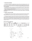
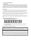
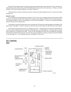
Heater Size Vent Connector Max Horizontal
Diameter Length - FT
260/261 8" 12.0
330/331 9" 13.5
400/401 10" 15.0
If installation requires horizontal runs, the vent pipe
must have a minimum of 1/4 inch per foot rise and
should be supported at not more than five foot
intervals.Plumbers tape, crisscrossed, will serve to
space both horizontal and vertical piping. Maximum
vent connector horizontal length shall be 1-1/2 feet (18
inches) for each inch of connector diameter as follows:
Fig. # 8246.6