


.
24
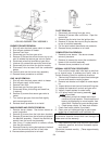
BURNER DRAWER REMOVAL
1. Shut off main electrical power switch to heater.
2. Shut off gas upstream of heater.
3. Remove front door.
4. Disconnect gas line from gas valve.
5. Remove (2) screws that mount burner tray to unit,
and (4) screws that secure gas valve to jacket.
6. Disconnect wires that terminate at gas valve.
7. Unscrew (4) screws that secure the control box.
8. Disconnect pilot wire from the ignition module.
9. Disconnect wire harness from the combustion
blower.
10. Carefully slide out the burner tray assembly.
11. Reverse above procedure to reinstall.
GAS VALVE REMOVAL
1. Shut off main electrical power switch to heater.
2. Shut off gas supply to the heater.
3. Remove front door.
4. Disconnect gas line from gas valve.
5. Disconnect wires, pilot tubing and bleed line,
if required.
6. Remove (2) screws that secure gas valve to
jacket.
7. Turn vertical gas pipe from manifold slightly
and unscrew gas valve.
8. Reverse above procedure to re-install.
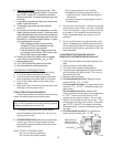
MAIN BURNER AND ORIFICE REMOVAL
1. Remove burner drawer. See burner drawer re-
moval procedure.
2. Remove (8) screws from the hold down brackets.
3. Remove (8) screws from the left and right sides of
the Manifold assembly. Detach the manifold as-
sembly from the burner tray assembly.
4. Use a long ½” socket wrench to remove orifices
from the gas manifold.
5. Remove burners by raising the bracket on the back
end of the burners up and out of their slots.
6. Reverse above procedure to re-install.
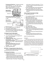
PILOT REMOVAL
1. Disconnect pilot tubing from gas valve.
2. Remove (4) screws from control box. Open the
control box.
3. Remove the pilot wire from the ignition wire.
4. Remove (2) screws that mount the pilot bracket
to the air manifold assembly.
5. Pull the pilot bracket downwards and outwards.
6. Reverse above procedure to re-install.
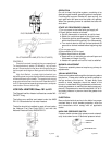
COMBUSTION FAN REMOVAL
1. Remove burner drawer. See burner drawer
removal procedure.
2. Remove (4) screws the mount the combustion
blower to the manifold assembly.
3. Reverse above procedure to re-install.
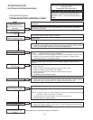
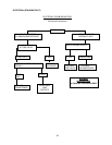
NORMAL INSPECTION PROCEDURES
First and third month after initial start up and then
on an annual basis. If problems are found, refer to
Trouble Shooting Guide for additional directions.
1. Remove top of heater and inspect heat exchanger
for soot and examine venting system.
2. Remove rear header and inspect for scale depos-
its.
*3. Inspect pilot and main burner flame and firing rate.
*4. Inspect and operate all controls and gas valve.
*5. Visually inspect system for water leaks.
*6. a.Oil pump motor and bearing assembly, if oil
cups are provided.
b. Disconnect pump from header and check
condition of pump impeller. Check condition of
bearing by attempting to move impeller from
side to side. Replace any parts showing wear.
c. Check pump coupler for wear and vibration.
7. Check flow switch paddle (if provided).
8. Clean room air intake openings to assure ade-
quate flow of combustion and ventilation air.
CAUTION: Combustion air must not be contaminated
by corrosive chemical fumes which can damage the
heater and void the warranty.
9. Keep heater area clear and free from combustible
materials, gasoline, and other flammable vapors
and liquids.
*Should be checked monthly. (Takes approximately
15 minutes).
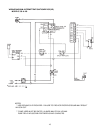
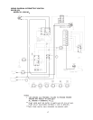
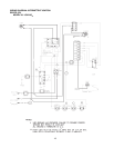
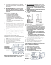
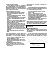
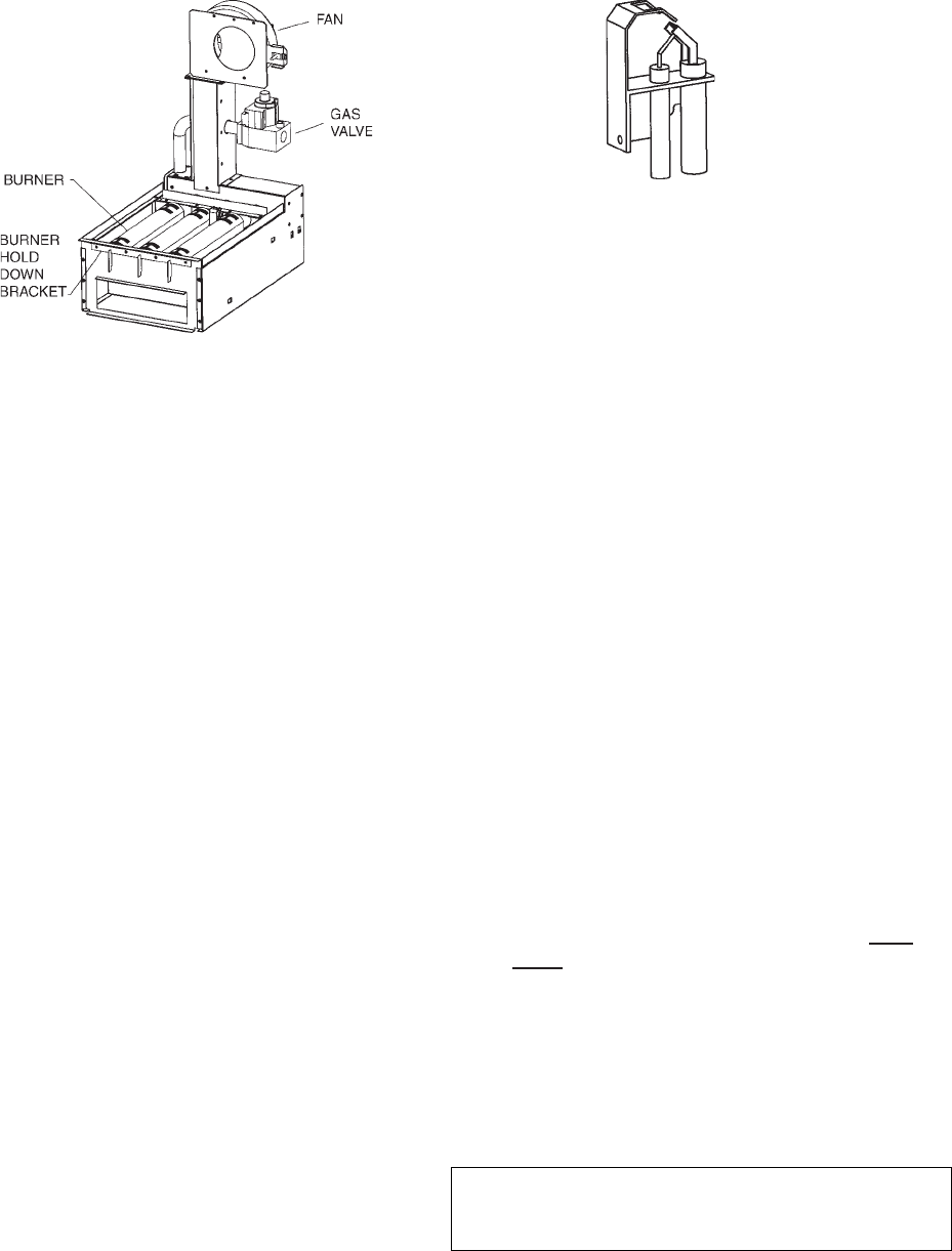
LOW NOx BURNER TRAY ASSEMBLY
Fig # 9363
IID PILOT