


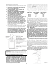

1) The heater must be provided with adequate supply
of air for proper combustion and ventilation in
accordance with the latest edition of the National
Fuel Gas Code, ANSI Z223.1, or applicable provi
sions of the local building codes.
2) When the heater is installed in a confined space
where all air is supplied from inside the building, the
heater room must be provided with two openings,
each one having a minimum net free area, in square
inches as follows:
Model Sq. In. Of Free Area
260 264
330 333
400 399
One opening shall be within 12 inches of the top, and the
other opening within 12 inches of the floor. If additional
gas appliances are installed in the same space, the total
input of all gas appliances installed in the same space,
must be considered in the calculation. Refer to Sec.
5.3.5 of the latest edition of the National Fuel Gas Code
for additional requirements.
NOTE: If louvers, grills or screens are used on the
openings, obtain the net free area from their supplier or
manufacturer. If the design free area of a louver is not
known nor available, it shall be assumed that wood
louvers will have 20-25 percent free area and metal
louvers will have 60-75 percent free area as shown in the
National Fuel Gas Code.
3. If the heater room is located against an outside wall
and air openings can communicate directly with the
outdoors, the two openings on the out side wall must
each have a net free area, in square inches as follows:
Model Sq. In. Of Free Area
260/261 66
330/331 84
400/401 100
Location of the openings is the same as in the previous
case - that is, within 12 inches of the top, and within 12
inches of the bottom of the enclosure. If horizontal ducts
are used, the area must be doubled and the duct area
shall not be less than the area of the openings they
connect, and in no case shall the smallest dimension be
less than 3 inches.
OUTDOOR MODELS
Heaters must not be installed under an overhang of
less than three (3) feet from the top on the heater. Three
(3) sides must be open in the area under the overhang.
Roof water drainage must be diverted away from the
heater installed under overhangs with the use of gutters.
The point from where the flue products exit the heater
must be a minimum of four (4) feet below, four (4) feet
horizontally from or one (1) foot above any door, window
or gravity inlet to a building. The top surface of the heater
shall be at least three (3) feet above any forced air inlet,
or intake ducts located within ten (10) feet horizontally.
In areas where high winds are frequent, it may be
necessary to locate the heater a minimum of 3' from high
vertical walls, or install a wind break so the heater is not
in direct wind current.
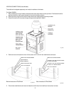
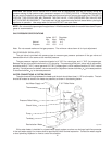
VENTING CONNECTIONS (Outdoor Models)
Outdoor vent top is shipped separately and must be
installed on site.
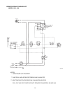
MODELS 260-401
Step 1: Insert screw retainer clip over mounting flange,
(4 places).
Fig. #8280.1
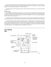
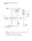
Step 2: Attach mounting angles to heater jacket with
1/2" sheetmetal screws, (4 places).
Fig. #8281.1
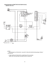
Step 3: Lower outdoor top to heater and secure with 1"
sheetmetal screws.
LONG SIDE OF MOUNTING
ANGLE LOCATED AS SHOWN
7