


10
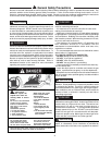
WARNING: These heaters must not be connected into
any portion of mechanical draft systems operating
under positive pressure. To do so may cause the flue
products to be discharged into the living space causing
serious health injury.
For connections to gas vents or chimneys, vent
installations shall be in accordance with Part 7, Venting
of Equipment, of the National Fuel Gas Code, ANSI
Z223.1, or applicable provisions of the local building
codes.
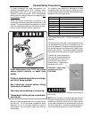
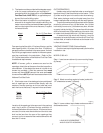
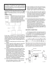
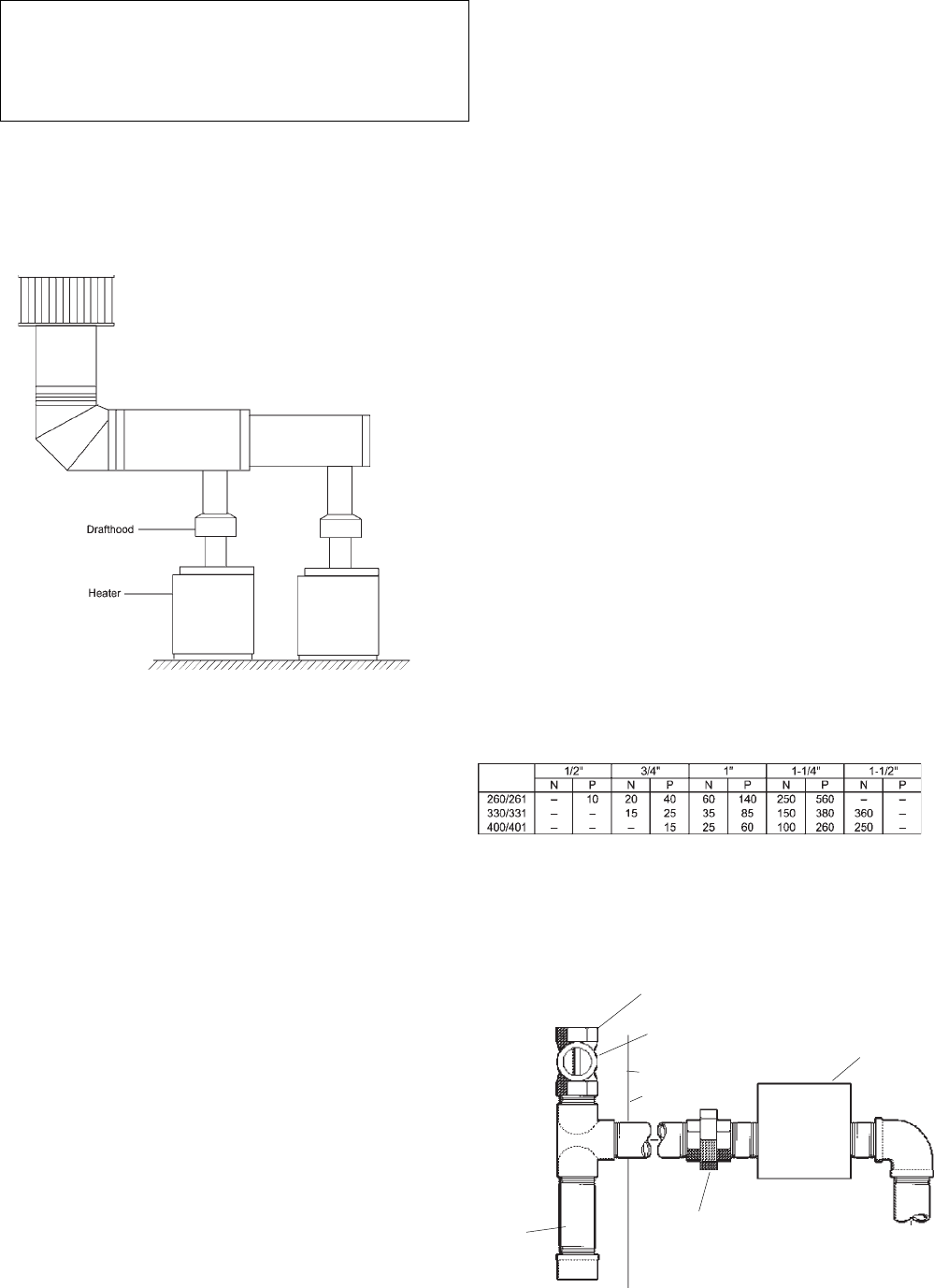
COMMON VENTS
Manifolds that connect more than one
heater to a common chimney must be
sized to handle the combined load.
Consult available guides for proper
sizing of the manifold and the chimney.
At no time should the area be less than
the area of the largest outlet.
At the time of removal of an existing heater, the
following steps shall be followed with each appliance
remaining connected to the common venting system
placed in operation, while the other appliances remain-
ing connected to the common venting system are not
in operation.
(a) Seal any unused openings in the common venting
system.
(b) Visually inspect the venting system for proper size
and horizontal pitch and determine there is no
blockage or restriction, leakage, corrosion and
other deficiencies which could cause an unsafe
condition.
(c) Insofar as is practical, close all building doors and
windows and all doors between the space in which
the appliances remaining connected to the com-
mon venting system are located and other spaces
of the building. Turn on clothes dryers and any
appliance not connected to the common venting
system. Turn on any exhaust fans, such as range
hoods and bathroom exhausts, so they will oper-
ate at maximum speed. Do not operate a summer
exhaust fan. Close fireplace dampers.
(d) Place in operation the appliance being inspected.
Follow the lighting instructions. Adjust tankstat
so appliance will operate continuously.
(e) Test for spillage at the draft hood relief opening
after 5 minutes of main burner operation. Use the
flame of a match or candle, or smoke from a
cigarette, cigar or pipe to visually check spillage.
(f) After it has been determined that each appliance
remaining connected to the common venting sys-
tem properly vents when tested as outlined above,
return doors, windows, exhaust fans, fireplace
dampers and any other gas burning appliance to
their previous conditions of use.
(g) Any improper operation of the common venting
system should be corrected so the installation con-
forms with the latest edition of the National Fuel
Gas Code, ANSI Z223.1. When re-sizing any
portion of the common venting system, the com-
mon venting system should be re-sized to
approach the minimum size as determined using
the appropriate tables in Chapter 10 and in appendix
Gof the National Fuel Gas Code, ANSI Z223.1 and
CAN/CSA-B149.1.
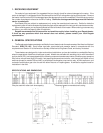
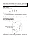
GAS SUPPLY CONNECTIONS
The inlet gas connection to the heater gas valve is
1/2" for model 203; 3/4" for models 260 and 330; and
1" for model 400. Provide an adequate gas supply line
no smaller than 1/2", according to the chart below:
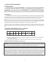
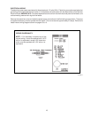
MAXIMUM EQUIVALENT PIPE LENGTH (FEET)
NATURAL GAS 1000 BTU/FT .60 SPECIFIC GRAVITY @ 0.5" W.C. PRESSURE DROP
PROPANE GAS 2500 BTU/FT 1.53 SPECIFIC GRAVITY @ 0.6" W.C. PRESSURE DROP
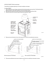
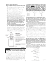
Gas piping must have a sediment trap ahead of the
boiler gas controls, and a manual shut-off valve located
outside the heater jacket. All gas piping should be tested
after installation in accordance with local codes.
Gas Inlet
Manual Shut Off Valve Gas
Valve
Heater Jacket
Fig. # 8090.1
Sediment
Trap
Union
Fig. # 9463