


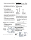
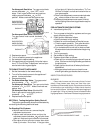
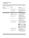
For Honeywell Gas Valve: Turn gas control knob
counter clockwise from “OFF” until it
stops. Push in gas control knob and continue
rotating counter clockwise to “ON”
position. Make sure knob rest against stop.
GAS CONTROL
KNOB SHOWN
IN "ON" POSITION
GAS INLET
Fig. #8082
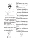
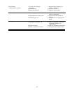
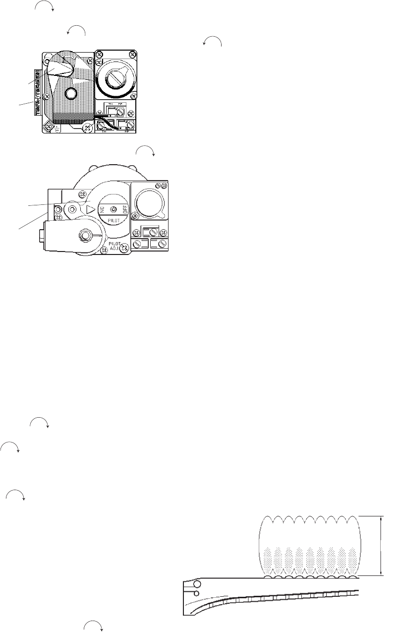
For Honeywell Gas Valve: (Models 403 )
Turn gas control knob counter clockwise
to “ON”.
GAS CONTROL
KNOB SHOWN
IN "ON" POSITION
GAS INLET
Fig. #8219.0
9. Replace door panel.
10. Turn on all electric power to the appliance.
11. Set tankstat to desired setting.
12. If the appliance will not operate, follow the instruc-
tions “To Turn Off Gas To Appliance” and call your
service technician or gas supplier.
TO TURN OFF GAS TO APPLIANCE
1. Set the thermostat to the lowest setting.
2. Turn off all the electric power to the appliance if
service is to be performed.
3. Remove door panel.
4. For Robertshaw Gas Valve: Turn gas control
knob clockwise to “OFF”.
For Honeywell Gas Valve: Turn gas control knob
clockwise to “OFF”. Make sure knob rest
against stop.
For Honeywell Gas Valve: (Models 403)
Push in gas control knob slightly and turn
clockwise to “OFF”.
5. Replace heater door panel.
SECTION 4. Testing the Ignition Safety Shut-off
The ignition system safety shutoff must be tested by
conducting the following method of tests:
For Standing Pilot Systems
a.With the main burners on, remove the pilot
adjustment cover screw.
b.Insert a small slot screw driver and turn the
adjustment screw clockwise until pilot flame
goes out. Note and count number of turns made.
c.Gas valve will shut off main burners after about
three (3) minutes. End of test. If the gas valve
22
will not shut off, follow the instructions "To Turn
Off Gas To Heater" and call service technician or
your gas supplier.
d.Return pilot adjustment screw counterclockwise
, same number of turns as in step (b).
e.Replace pilot adjustment cover screw, then fol-
low the lighting instructions to get heater ready for
operation.
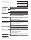
FOR AUTOMATIC IGNITION SYSTEMS
A. Intermittent Ignition (IID)
1. Turn on power to the ignition systems and turn gas
supply off at the gas valve.
2. Check ignition module as follows:
a.Set the tankstat to high setting.
b.Watch for continuous spark at the pilot burner.
c.Time the spark operation. Time must be within
the lockout timing period (15 or 90 seconds).
d.Turn tankstat down to end call for heat and wait
60 seconds on lockout models before beginning
step 3.
3. Turn on gas supply.
4. Set tankstat to high setting.
5. Systems should start as follows:
a.Spark will turn on and pilot gas valve will open at
once. Pilot burner should ignite after gas reaches
the pilot burner.
b.Spark ignition should cut off when pilot flame is
established.
c.Main gas valve should open and main burner
should ignite after gas reaches the burner port.
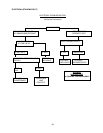
INSPECTION PROCEDURES
BURNERS
Clean main burners and air louvers of dust, lint and
debris. Keep heater area clear and free from com-
bustibles and flammable liquids. Do not obstruct the flow
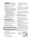
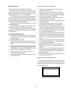
of combustion and ventilating air. Make visual check of
burner and pilot flame. Yellow flame indicates clogging of
air openings. Lifting or blowing flame indicates excess
high gas pressure. Low flame indicates low gas pressure.
4" Max.
TYPICAL MAIN BURNER FLAME
Fig. # 8144