


48
9. DO NOT apply excessive torque during rolling
operation and avoid thinning any wall of the tube
beyond 0.015".
10. Use same procedure on opposite end.
11. Apply line pressure test. Re-roll if necessary.
12. Reinstall as outlined under HEAT EXCHANGER
REASSEMBLY.
5.*72705>.*<
*<<*0.@*B<
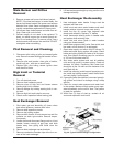
Soot will clog areas between fins and cause eventual
tube failure. Any sign of soot at base of burners or
around outer jacket indicates a need for cleaning.
1. Lift off drafthood and flue collector by removing
bolts and screws.
2. Remove "V" baffles from heat exchanger.
3. Remove burner tray.
4. Take garden hose and wash heat exchanger, mak-
ing sure soot is removed from between fins. (Avoid
excessive water against refractory).
5. Reassemble: When heater is fired, some steam
will form from wet refractory. This is normal.
6. Identify and correct reason for soot formation.
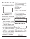
" $ "$#
See separate parts sheet in instruction envelope.
Any part returned for replacement under standard
company warranties must be properly tagged with
RAYPAK return parts tag, completely filled in with the
heater serial number, model number, etc., and shipped
to the Company freight prepaid. If determined defec-
tive by the Company and within warranty, the part will
be returned in kind or equal substitution, freight collect.
Credit will not be issued.
RAYPAK, INC.
2151 Eastman Avenue
Oxnard, CA 93030
$ In extreme cases it may be necessary to
remove the heat exchanger completely for cleaning.
The simplest method is high pressure cleaning at a
local car wash. DO NOT WIRE BRUSH!
%$ Soot is combustible, so exercise
extreme care.
$ To supply the correct part it is important that
you state the model number, serial number and type
of gas when applicable.
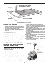
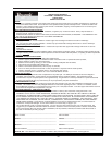
86+><=2871*6+.;".68?*5
To remove combustion chamber refractory you must
first have removed the heat exchanger. Unbolt metal
combustion chamber retainer from top and remove
refractory panels individually.
87=;85'.55".95*,.6.7=
Remove top, sensing bulb and clip. Collapse well tube
at the open and with a chisel, push through into head-
er and remove the well through header. Insert a new
well and roll into place. If a roller is not available, sol-
der the well in place with silver solder.
$>+.".95*,.6.7=
1. Remove heat exchanger from heater following
instructions outlined under HEAT EXCHANGER
REMOVAL on page 45.
2. Remove in/out and return headers. Remove "V"
baffle from damaged tube.
3. Remove damaged tube by cutting with a hack saw
or shearing with a chisel adjacent to each tube
sheet.
4. Collapse stub ends in tube sheets using a chisel or
screwdriver. DO NOT cut into tube sheet or mar
surface in tube hole in any way.
5. Insert replacement tube by inserting the end with
the most fins removed in the opening of one tube
sheet. Slide tube until the opposite end clears the
other tube sheet and fit the tube into the hole.
6. Insert the tube roller into tube opening up to stop,
making certain that 1/8" of tube projects beyond
the tube sheet.
7. Attach drill to tube roller, holding it straight and
level. Note: Use a 3/8" heavy duty, reversible,
electric drill or larger. Proceed to expand tube until
tool starts to grab. Approximately 1/2 to 1" of the
tool shank will be visible.
8. Reverse drill motor and withdraw tube roller, If
necessary wrench out by hand.
Fig. 41: Refractory Panels—Top View