27
258=#*/.=B
Models 0514-4001 employ electronic devices which
close the main gas valve within 8/10 of a second
whenever the pilot flame is interrupted. Pilot flame is
a
utomatically lit when the device is powered. Unit per-
forms its own safety check and opens the main valve
only after the pilot is proven to be lit.
8@'*=.;>=//9=287*5
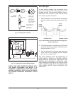
The low water cut-off automatically shuts down burner
whenever water level drops below probe. 5-second
(max) time delay prevents premature lockout due to
temporary conditions such as power failure or air
pockets. Flush float type devices at beginning of each
heating season.
201*7-8@*< ;.<<>;.
#@2=,1.<9=287*5
These switches sense either high or low gas pres-
sures and automatically shut down burners if abnormal
pressures exist.
5.,=;2,*5877.,=287<
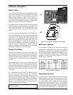
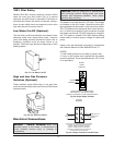
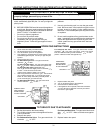
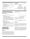
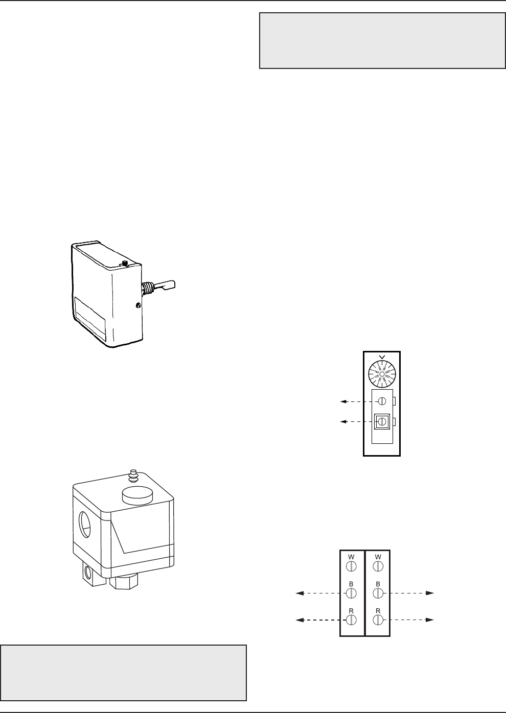
Fig. 27: Low Water Cut-Off
Fig. 28: Gas Pressure Switch
The heater is normally wired for 120 Volts. The voltage
is indicated on the tie-in leads. Consult the wiring dia-
gram shipped with the heater in the instruction packet.
The "TH" leads are for the remote tank control connec-
tion. 24 Volts are supplied to this connection through
the heater transformer. DO NOT attach line voltage to
the "TH" leads on models 0514-1826. Before starting
heater check to ensure proper voltage to heater and
pump.
Heater must be electrically grounded in accordance
with National Electrical Code ANSI/NFPA No 70.
NOTES:
1. Field install ground wire to inside of junction box.
2. If any of the original wire supplied with the heater
must be replaced, it must be replaced with 105°C wire
or its equivalent.
%$ Label all wires prior to disconnection
w
hen servicing controls. Wiring errors can cause
improper and dangerous operation. Verify proper
operation after servicing.
" # )" Make sure
electrical power to the heater is disconnected to
avoid potential serious injury or damage to
components.
SINGLE
STAGE
TANKSTAT
STAGE 1
CONNECTION
ATTACH STAGE 1 CONNECTIONS
ON HEATER TO THE SINGLE STAGE
TANKSTAT AS SHOWN IN THE DIAGRAM ABOVE.
2-STAGE
TANKSTAT
STAGE 1
CONNECTION
STAGE 2 CONNECTION OR
STAGE 1 CONNECTION
OF HEATER 2
ATTACH STAGE 1 CONNECTIONS ON HEATER
TO STAGE 1 CONNECTION ON TANKSTAT.
ATTACH STAGE 2 CONNECTIONS OR
STAGE 1 CONNECTION OF HEATER 2
TO STAGE 2 CONNECTION ON TANKSTAT
AS SHOWN IN THE DIAGRAM.
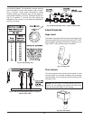
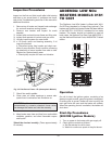
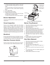
Fig. 29: Single-Stage Tankstat
Fig. 30: 2-Stage Tankstat (2 On/Off Units)


