


47
*27>;7.;*7-;2/2,.
".68?*5
1
. Remove screws and burner hold-down bracket.
NOTE: If the heat exchanger is sooted badly, the
b
urner hold-down bracket and spacer can become
distorted from direct flame impingement and this
usually necessitates replacement of these parts.
2. Lift burners from slotted spacer and slide from ori-
fices. Clean with a wire brush.
3. Orifices usually do not need to be replaced. To
clean, run either copper wire or wood through ori-
fice. Do not enlarge hole. To remove orifice, use a
socket wrench and remove the manifold. DO NOT
overtighten when reinstalling.
258=".68?*5*7-5.*7270
1. Disconnect pilot tubing at pilot and sensor/igniter
wire. Remove screws holding pilot bracket to burn-
er tray.
2. Remove pilot and bracket, clean pilot of debris,
small bugs, etc., with wire or small brush.
3. Replace pilot, pilot tubing, sensor ignition wires
and check for leaks.
201262=8;$*74<=*=
".68?*5
1. Turn off electrical power.
2. Remove front inspection panel.
3. Remove wires to high limit and loosen screws
holding high limit to cabinet.
4. Remove wedge clip holding sensing bulb in con-
trol well.
5. Remove high limit and install a new one.
6. Check control operation before leaving job.
.*=A,1*70.;".68?*5
1. Shut water, gas and electricity off, close valves
and relieve pressure, remove relief valve.
2. Remove side inspection panels.
3. Remove top holding screws.
4. Remove draft diverter, lift and remove top and flue
collector on stack type models. Remove inspec-
tion panels.
5. Loosen bolts and disconnect flange nuts on in/out
header, loosen union(s) at gas pipe, and slide
heater away from piping until studs clear the
heater.
6. Remove heat exchanger corner brackets.
7. Remove combustion chamber clips at the four cor-
ners of the heat exchanger.
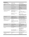
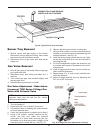
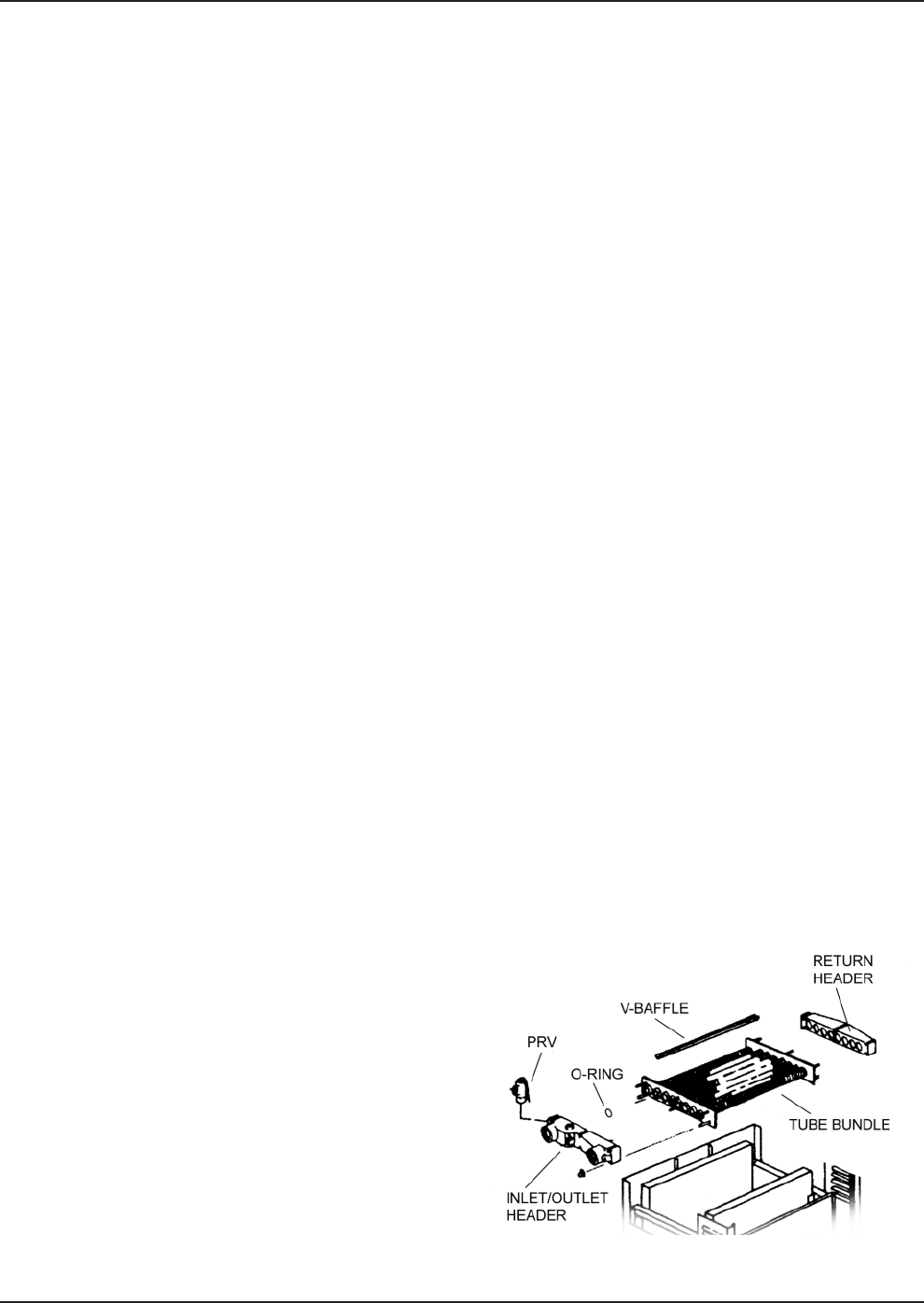
Fig. 40: Typical Heat Exchanger Configuration
8. Lift heat exchanger straight up using caution not to
damage refractory.
.*=A,1*70.;".<<.6+5B
1. Heat exchanger water header O-rings must be
r
eplaced with new ones.
2. Install in/out and return water headers and install
header retainer nuts and torque nuts evenly.
3. Install the four (4) corner clips between tube
sheets and refractory. Replace "V" baffles.
4. Install thermostat sensing bulbs in header wells
and replace bulb retaining clips.
5. Install inlet and return pipes in water headers
using pipe thread sealant.
6. Install water pressure relief valve, flow switch, and
low water cut-off devices (if so equipped).
7. Open water supply and return shut-off valves. Fill
heater and water piping system with water. Check
heater and piping system for leaks at full line pres-
sure. Run system circulating pump for a minimum
of 1/2 hour with heater shut-off.
8. Shut down entire system and vent all radiation
units and high points in system piping. Check all
strainers for debris. Expansion tank water level
should be at the 1/4 mark and the balance of the
tank filled with air.
9. Install flue collector, jacket top and inspection pan-
els. Install top holding screws. Install draft diverter
and vent piping if so equipped.
10. If gas piping was disconnected, reconnect gas pip-
ing system and check for leakage using a soap
solution.
11. Check for correct water pressure and water level
in the system. Make sure that system pump oper-
ates immediately on the call for heat. The system
is ready for operation.
12. Within two (2) days of start-up, recheck all air
vents and expansion tank levels.