


61
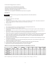
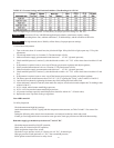
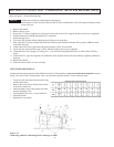
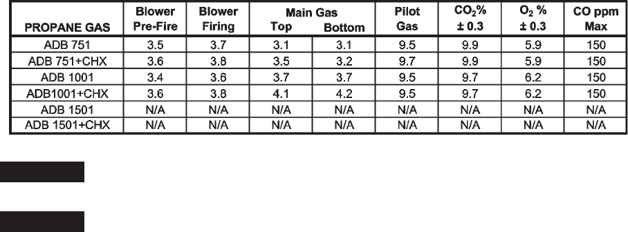
TABLE O-3: Pressure Settings and Emission Guidelines (True Readings) for LP GAS
Note: For different gas control options, call the factory for proper pressure settings (i.e. IRI, etc)
NOTICE: Emissions will vary with different applications (hydronic, water heater, or pool), venting
(including direct vent), ambient conditions (T, P, and humidity), and the condition of the boiler.
NOTICE: For high altitude (above 5000 ft), call the factory for proper pressure settings.
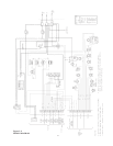
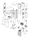
3.3 Main Burner Adjustment
1. Turn on the unit; about 45 seconds later, the pilot should light. If the pilot fails to light, repeat step 3.2 for pilot
adjustment;
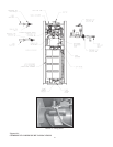
2. Turn the top manual valve on, Location (2). The inner burner will fire;
3. Make sure that the supply gas manometer reads between 7 – 14” W.C. (dynamic pressure);
4. Check manifold pressure, Location (2); this should read to within ± 0.1” W.C. of the values shown in tables O-2 and
O-3;
5. If adjustment is required, remove screw cap off the top gas pressure regulator, and adjust regulator;
6. Slowly turn the bottom manual valve on, Location (3). The outer burner will fire;
7. Make sure that the supply gas manometer reads between 7 – 14” W.C. (dynamic pressure);
8. Check manifold pressure, Location (3); this should read to within ± 0.1” W.C. of the values shown in tables O-2 and
O-3;
9. If adjustment is required, remove screw cap off the bottom gas pressure regulator, and adjust regulator;
10. The blower pressure should increase about 3/10” (0.3”) W.C. equaling the “Firing” value in tables O-2 and O-3;
11. Lock the blower shutter by tightening the shutter nut while holding the black knob fixed;
12. Allow minimum 5 minutes of run time; then attach flue analyzer, check emission and compare the CO
2
reading to that
of table O-2 & O-3;
13. If CO
2
is high, reduce bottom manifold gas pressure;
14. If CO
2
is low, increase the bottom manifold gas pressure;
15. All pressure readings especially manifold pressures should be within ±0.1” of listed values;
16. Replace the screw caps back on the gas regulators.
Your ADB is tuned in!
3.4 Safety Inspection
· Check thermostat and high limit settings.
· Attach thermometers to IN/OUT piping and take temperature measurement, see Table D-1and F-1 for correct flow
balance.
· During the following safety checks leave manometers, and analyzer hooked up, check and record.
· If other gas fired equipment in the room and on same gas main, check gas pressures on ADB with them running.
Remember supply gas should always be between 7” and 14" W.C.
· Check thermostat control for ON/OFF operation;
· Check safety Hi Limits for ON/OFF operation;
· While in operation inspect flow switch;
· Check the low gas pressure switch, it is factory set at 6" W.C. for natural gas;
· High gas pressure switch (optional) at 1" W.C. above manifold pressure;
· Insert ignition control lockout test as safety check.