


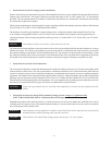
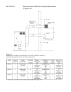
• Natural Draft Vertical Venting System Installation
Natural draft venting uses the natural buoyancy of the heated flue products to create a thermal driving head that expels the
exhaust gases from the flue. The negative draft must be within the range of 0.01 to 0.08” negative W.C. to insure proper
operation. The vent material must be in accordance with the above instructions for vent materials. Vent material must be listed
by a nationally recognized test agency.
The maximum and minimum venting length for Category I appliance shall be determined per the latest edition of the National
Fuel Gas Code (U.S.) or B179.1 and .2 Installation Code (Canada).
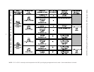
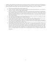
The diameter of vent flue pipe should be sized according to Part 11 of the latest edition of the National Fuel Gas Code
(U.S.) and part 7 and appendix B of the CAN/CGA-B149.1 and .2 installation code (Canada). The flue pipe diameter for
conventional negative draft venting using double-wall B type vent is 8” for the ADB 751, 10” for the 1001, and 12” for the
ADB 1501.
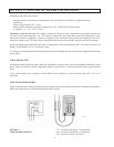
NOTICE: Vent Adapter will have to be used to connect B vent to the unit.
The connection from the appliance vent to the stack must be as direct as possible and shall be the same diameter as, or larger
than the vent outlet. The vent must be installed to prevent accumulation of condensate and, where necessary, have means
provided for drainage of condensate. The horizontal breaching of a vent must have an upward slope of not less than 1/4 inch
per linear foot from the boiler to the vent terminal. The horizontal portions of the vent shall also be supported for the design
and weight of the material employed to maintain clearances and to prevent physical damage or separation of joints.
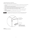
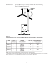
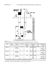
• Natural Draft Vertical Vent Termination
The vent terminal should be vertical and should terminate outside the building at least two (2) feet above the highest point
of the roof that is within 10 feet. The vent cap should have a minimum clearance of four (4) feet horizontally from and in no
case above or below (unless a four (4) foot horizontal distance is maintained) electric meters, gas meters, regulators and relief
equipment. The distance of the vent terminal from adjacent public walkways, adjacent buildings, open windows and building
openings must be consistent with the National Fuel Gas Code, or in Canada, the latest edition of CAN/CGA-B149 Instal-
lation Code for Gas Burning Appliances and Equipment. Gas vents supported only by flashing and extended above the roof
more than five feet should be securely guyed or braced to withstand snow and wind loads.
CAUTION: Listed vent cap terminal must be used and sized adequately to evacuate the flue products from the
boilers.
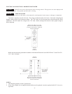
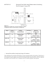
• Natural Draft Vertical Venting With Common Venting System, Category I Appliance Only
(NOT To Be Utilized With Add-on Condensing Heat Exchanger)
Manifolds that connect more than one boiler to a common chimney must be sized to handle the combined load. Consult
available guides for proper sizing of the manifold and the chimney. At no time should the area of the vent be less than the
area of the largest boiler exhaust outlet.
WARNING: Vent connectors serving appliances vented by natural draft shall not be connected into any portion of
mechanical draft systems operating under a positive pressure.
CAUTION: Vent connectors for natural draft venting systems must be type “B” vent or better.
32