


25
MAKING THE ELECTRICAL CONNECTIONS
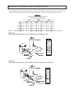
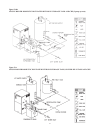
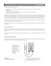
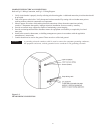
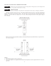
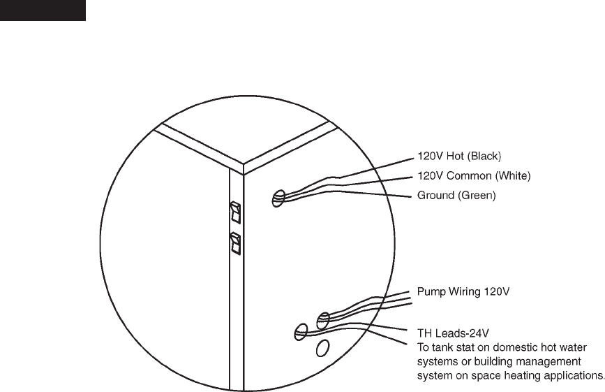
Refer to Fig. I-2 Wiring Connection, and Fig. L-2 Wiring Diagram.
1. Verify circuit breaker is properly sized by referring to boiler rating plate. A dedicated motor duty circuit breaker should
be provided.
2. Turn off all power to the boiler. Verify that power has been turned off by testing with a volt-ohm meter prior to
working with any electrical connections or components.
3. Observe proper wire colors while making electrical connections. Many electronic controls are polarity
sensitive. Components damaged by improper electrical installation are not covered by warranty.
4. Provide an external surge suppressor capable of maintaining system integrity.
5. Provide overload protection and a disconnect means for equipment serviceability as required by local and
state code.
6. Install boiler controls, thermostats, or building management systems in accordance with the applicable
manufacturer’s instructions.
7. Conduit should not be used as the ground. There must be a solid wired ground.
NOTICE: A grounding electrode conductor shall be used to connect the equipment grounding conductors,
the equipment enclosures, and the grounded service conductor to the grounding electrode.
Figure I-2
FIELD WIRING CONNECTION