


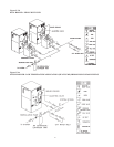
SECTION D: WATER PIPING - GENERAL
The boiler should be located so that any water leaks will not cause damage to the adjacent area or structures.
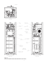
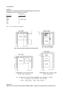
All units should be plumbed in accordance with the appropriate diagram from Section E, F or G or per a suitable engineered
piping arrangement.
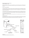
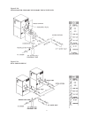
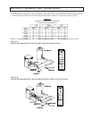
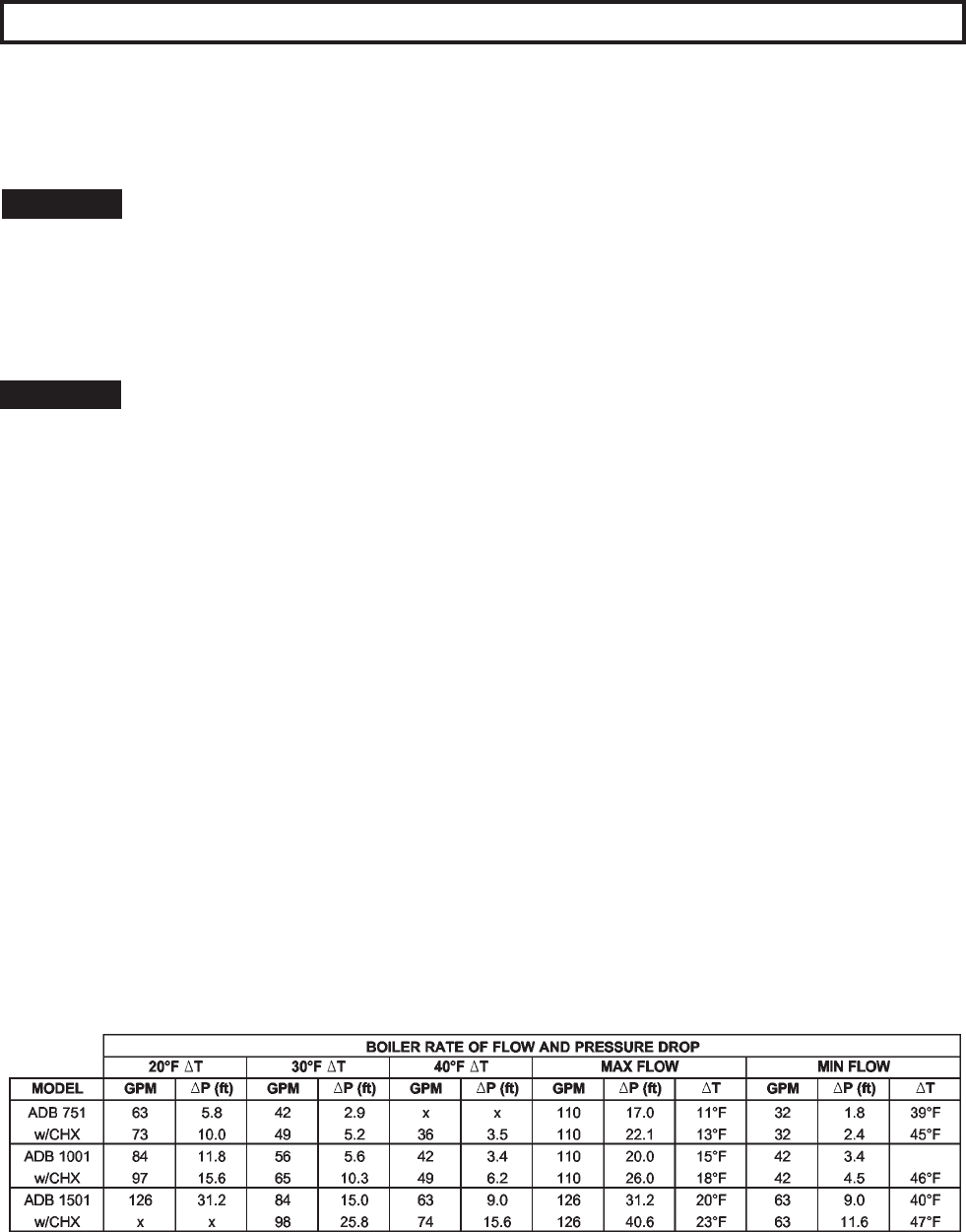
CAUTION: This boiler requires forced water circulation when the burner is operating. See Table D-1 for
minimum and maximum flow rates and water pump selection. The pump must be interlocked with the
boiler to prevent boiler operation without water circulation. See Figure L-2 Wiring Diagram and
Figure L-1.
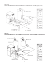
RELIEF VALVE PIPING
WARNING: Pressure relief valve discharge piping must be piped near the floor close to a floor drain to eliminate
the potential of severe burns. Do not pipe to any area where freezing could occur. Refer to local codes.
HYDROSTATIC TEST
Unlike many other types of boilers, Raypak boilers do not require hydrostatic testing prior to being placed in operation.
The heat exchanger has already been factory-tested and is rated for 150 PSI operating pressure. However, Raypak does
recommend hydrostatically testing the piping connections to the boiler and the rest of the system prior to operation. This
is particularly true for hydronic systems using expensive glycol-based antifreeze. Raypak recommends conducting the
hydrostatic test before connecting gas piping or electrical supply.
Leaks must be repaired at once to prevent damage to the boiler. NEVER use petroleum-based stop-leak compounds.
1. Connect fill water supply. Fill boiler with water (be sure bleed valve is open). When water flows from bleed
valve, shut off water. Close bleed valve. Carefully fill the rest of the system, being sure to eliminate any
entrapped air by using high point vents. Close feed valve. TEST AT standard operating pressure for at least 24 hours.
2. Make sure constant gauge pressure has been maintained throughout test.
3. Check for leaks. Repair if found.
LOW TEMPERATURE SYSTEM
Boiler requires minimum inlet temperature of 105°F. Consult sections E, F or G for piping details. (For Pool temperature
requirements, See Section G).
TEMPERATURE & PRESSURE GAUGE
The temperature and pressure gauge is factory-mounted in the inlet/outlet header.
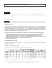
Table D-1
Delta P Should include typical piping To/From a single tank as well as bypass piping.
NOTE: GPM flow rates limited by maximum acceptable velocity through heat exchanger tubes. May be
increased by 10% for closed heating systems. Pressure drop would increase by 21%.
12