


9. Install flue collector, jacket top and inspection pan-
els. Install top holding screws. Install draft diverter
and vent piping if so equipped.
10. If gas piping was disconnected, reconnect gas pip-
ing system and check for leakage using a soap
solution.
11. Check for correct water pressure and water level
in the system. Make sure that system pump oper-
ates immediately on the call for heat. The system
is ready for operation.
12. Within two (2) days of start-up, recheck all air
vents and expansion tank levels.
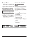
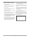
Combustion Chamber Removal
To remove combustion chamber panels, you must first
remove the heat exchanger. Remove combustion
chamber panels individually.
33
Heat Exchanger Re-assembly
1. Heat exchanger water header O-rings should be
replaced with new ones.
2. Install in/out and return water headers and install
header retainer nuts and torque nuts evenly.
3. Replace "V" baffles.
4. Install thermostat sensing bulbs in header wells
and replace bulb retaining clips.
5. Install inlet and return pipes in water headers
using pipe thread sealant.
6. Install water pressure relief valve, flow switch, and
low water cut-off devices if so equipped.
7. Open water supply and return shut-off valves. Fill
boiler and water piping system with water. Check
boiler and piping system for leaks at full line pres-
sure. Run system circulating pump for a minimum
of 1/2 hour with boiler shut off.
8. Shut down entire system and vent all radiation
units and high points in system piping. Check all
strainers for debris. Expansion tank water level
should be at the 1/4 mark and the balance of the
tank filled with air (when using Air-X-Tank).
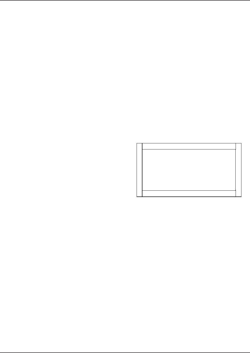
Fig. 36: Combustion Chamber Panels—Top View