


11
At the time of removal of an existing boiler, the follow-
ing steps shall be followed with each appliance
remaining connected to the common venting system
placed in operation, while the other appliances remain-
ing connected to the common venting system are not
in operation.
1. Seal any unused openings in the common venting
system.
2. Visually inspect the venting system for proper size
and horizontal pitch and make sure there is no
blockage or restriction, leakage, corrosion and
other deficiencies which could cause an unsafe
condition.
3. Insofar as is practical, close all building doors and
windows and all doors between the space in which
the appliances remaining connected to the com-
mon venting system are located and other spaces
of the building. Turn on clothes dryers and any
appliance not connected to the common venting
system. Turn on any exhaust fans, such as range
hoods and bathroom exhausts, so they will oper-
ate at maximum speed. Do not operate a summer
exhaust fan. Close fireplace dampers.
4. Place in operation the appliance being inspected.
Follow the lighting instructions. Adjust thermostat
so appliance will operate continuously.
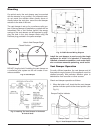
5. Test for spillage at the drafthood relief opening
after 5 minutes of main burner operation. Use the
flame of a match or candle, or smoke from a ciga-
rette, cigar or pipe to visually check spillage.
6. After it has been determined that each appliance
remaining connected to the common venting sys-
tem properly vents when tested as outlined above,
return doors, windows, exhaust fans, fireplace
dampers and any other gas burning appliance to
their previous conditions of use.
7. Any improper operation of the common venting
system should be corrected so that the installation
conforms with the latest edition of the National
Fuel Gas Code, ANSI Z223.1. When resizing any
portion of the common venting system, the com-
mon venting system should be resized to
approach the minimum size as determined using
the appropriate tables in Chapter 10 and in
Appendix G of the National Fuel Gas Code, ANSI
Z 223.1 and CSA - B149.
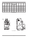
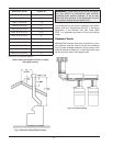
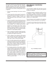
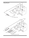
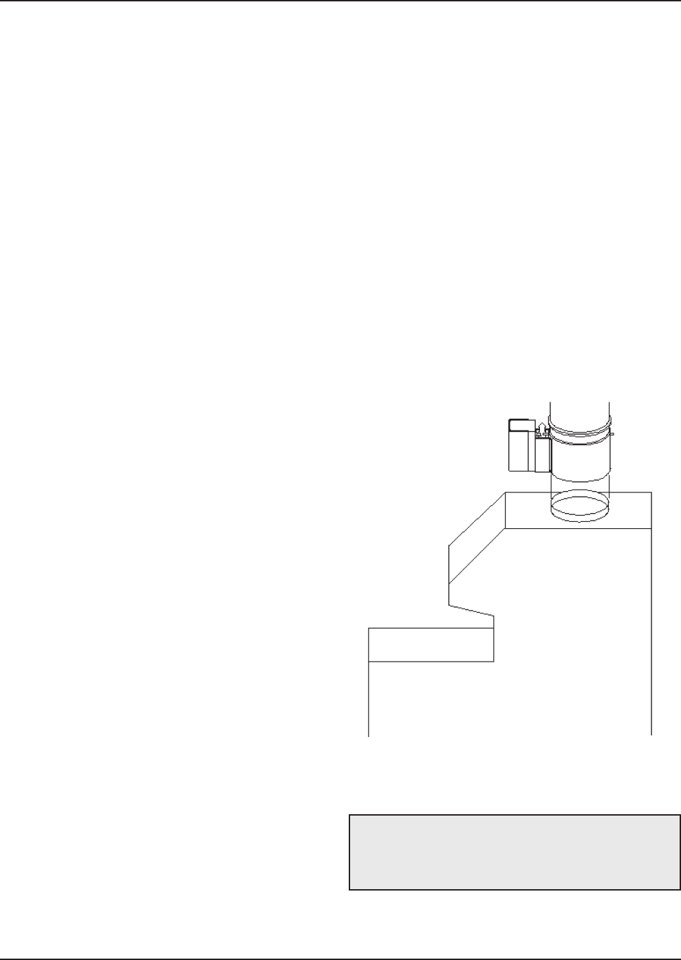
Vent Damper Installation
Location
The vent damper supplied with each boiler must be
located in the vent so that it serves only the appliance
for which it is intended.
If improperly installed, a hazardous condition, such as
an explosion or carbon monoxide poisoning, could
result. Make certain that it is mounted in an accessible
location at least 6 in. (152.4 mm) from any combustible
material or the heat exchanger and that the position
indicator is in a visible location.
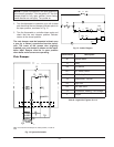
The vent damper must be installed at the appliance
drafthood, and without modification of the drafthood.
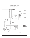
To connect the vent damper wiring to the boiler wiring,
connect the damper circuit plug to the boiler circuit
plug.
Fig. 7: Vent Damper Location
WARNING: Carefully read and follow the
installation instructions furnished with the vent
damper package. Failure to follow these instructions
can cause asphyxiation, explosion or fire.