


July 29, 2008
Page 9
Quadra-Fire · Castile Gas Stove · 7023-111E
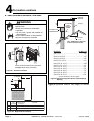
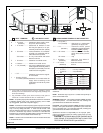
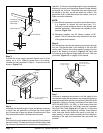
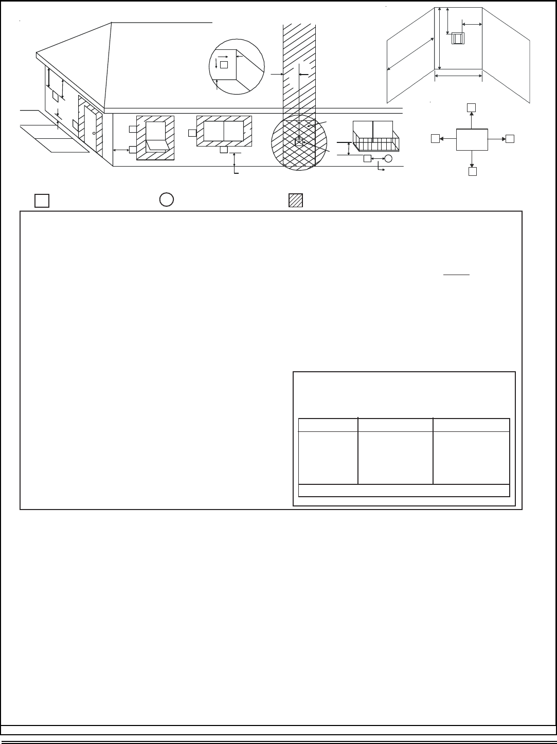
Figure 4.4
V
= VENT TERMINAL
X
= AIR SUPPLY INLET = AREA WHERE TERMINAL IS NOT PERMITTED
A = 12 inches ............. clearances above grade, veran-
da, porch, deck or balcony
B = 12 inches ............ clearances to window or door
that may be opened, or to per-
manently closed window. (Glass)
D* = 18 inches ............. vertical clearance to unventilat-
ed soffit or to ventilated soffit lo-
cated above the terminal
*30 inches............ for vinyl clad soffits and below
electrical service
F = 9 inches .............. clearance to outside corner
G = 6 inches ............... clearance to inside corner
H = 3 ft. (Canada) ...... not to be installed above a gas
meter/regulatorassemblywithin3
feet (90cm) horizontally from the
center-lineof the regulator
I
= 3 ft. ................
.......
clearance to gas service regula-
tor vent outlet
J = 9 inches (U.S.A.)
12 inches (Canada)clearance to non-mechanical air
supply inlet to building or the
combustion air inlet to any other
appliance
K = 3ft. (U.S.A.)
6 ft. (Canada) ......... clearance to a mechanical
(powered) air supply inlet
L** = 7 ft. ......................... clearance above paved
sidewalkor a paveddriveway
locatedonpublicproperty
M*** = 18 inches .............. clearance under veranda,
porch,deck, balcony or over-
hang
42 inches .............. vinyl
** a vent shall not terminate directly above a sidewalk or paved
driveway which is located between two single family dwellings and
serves both dwellings.
*** only permitted if veranda, porch, deck or balcony is fully open on
a minimum of 2 sides beneath the floor, or meets Note 2.
(SeeNote1)
(SeeNote 1)
S = 6 inches ................. clearance from sides of
electrical service
T = 12 inches ................ clearance above electrical
service
(SeeNote 3)
(See Note 3)
___________________________________________________________________
_
___________________________________________________________________
_
___________________________________________________________________
_
_
Q
MIN
R
MAX
1cap 3feet 2xQ
ACTUAL
2 caps 6 feet 1 x Q
ACTUAL
3 caps 9 feet 2/3 x Q
ACTUAL
4caps 12feet 1/2xQ
ACTUAL
Q
MIN
= # termination caps x 3 R
MAX
= (2 / # terminationcaps) xQ
ACTUAL
N = 6 inches................. non-vinyl sidewalls
12 inches............... vinyl sidewalls
P=8ft.
Alcove Applications
NOTE 1: Onprivate propertywhere termination is less than7 feetabove
a sidewalk, driveway, deck, porch, veranda or balcony, use of a listed
cap is suggested. (See vents components pages.)
NOTE 2: Terminationin analcove space (spaces onlyopen on one side
and
without
an overhang) are permitted with the dimensions specified for
vinyl or non-vinyl siding and soffits. 1. There must be at least 3 feet
minimum between termination caps. 2.All mechanical air intakes within
10 feet of a termination cap must be a minimum of 3 feet below the
termination cap. 3.All gravity air intakes within3 feetof atermination cap
must be a minimum of 1 foot below the termination cap.
NOTE 3: Location of the vent terminationmust not interfere with access
to the electrical service.
NOTE: Local codes or regulations may require different
clearances.
NOTE: Termination caps may be hot. Consider their proximity to
doors or other traffic areas.
WARNING: In the U.S.: Vent system termination is NOT permitted
in screened porches. You must follow side wall, overhang and
ground clearances as slated in the instructions.
In Canada: Vent system termination is NOT permitted in screened
porches. Vent system termination is permitted in porch areas with
two or more sides open. You must follow side wall, overhang and
ground clearances as stated in the instructions.
Quadra-Fire assumes no responsibility for the improper perfor-
mance of the appliance when the venting system does not meet
these requirements.
(See Note 2)
Electrical
Service
V
S
V
S
V
T
D*
V
D
E
B
L
v
v
v
v
v
v
v
v
B
B
A
H
M
X
J or K
I
A
G
F
U.S.
(3 FT)
B
M
N
P
R
Q
CAUTION: IF EXTERIOR WALLS ARE FINISHED WITH
VINYL SIDING, IT IS SUGGESTED THAT A VINYL PRO-
TECTOR KIT BE INSTALLED (part #VPK-DV).