


Page 16
July 29, 2008
Quadra-Fire · Castile Gas Stove · 7023-111E
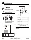
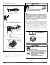
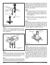
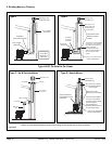
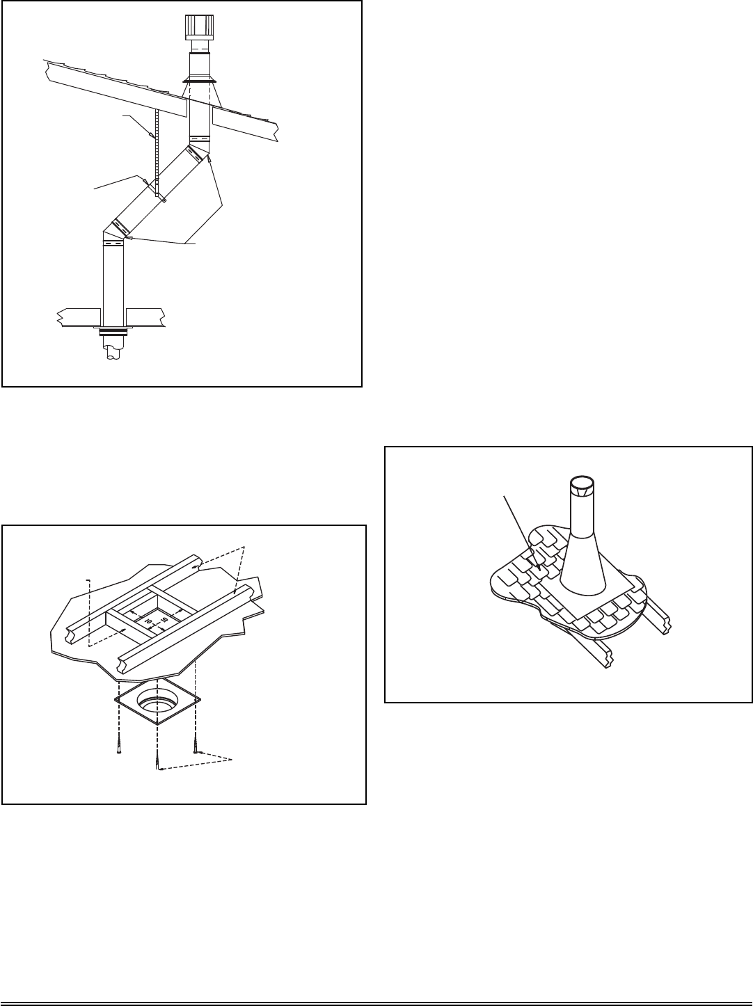
Plumber’s Tape
connected to
Wall Strap
Wall Strap
Two 45˚ Elbows
Figure 5.12
Step 4.
Assemble the desired lengths of pipe and elbows necessary
to reach from the appliance up through the round support
box. Ensure that all pipe and elbow connections are in their
fully twist-locked position. Assemble as instructed.
Step 5.
Cut a hole in the roof centered on the small drill hole placed in
the roof in Step 2. The hole should be of sufficient size to meet
the minimum requirements for clearance to combustibles, as
NOTE:
(1
) If an offset is necessary in the attic to avoid obstructions,
it is important to support the vent pipe every 3 ft.
(914mm) to avoid excessive stress on the elbows, and
possible separation. Wall straps are available for this
purpose, Figure 5.12.
(2) Whenever possible, use 45° elbows, instead of 90°
elbows. The 45° elbow offers less restriction to the flow
of flue gases and intake air.
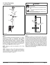
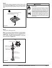
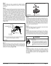
Step 7.
Continue to assemble pipe sections until the height of the
vent (before adding the termination cap) meets the minimum
code requirements as outlined in the current CAN/CGA-B149
Installation Codes (in Canada), the National Fuel Gas Code
NFPA 54/ANSI Z223.1 (in USA), or local codes. Note that
for steep roof pitches, the vent height must be increased.
See Roof Pitch Table (Figure 4.3, on page 8). In high wind
conditions, nearby trees adjoining rooflines, steep pitched
roofs, and other similar factors can result in poor draft, or
down drafting. In these cases increasing the vent height or
switching to the high wind termination cap may solve this
problem.
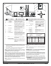
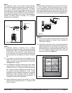
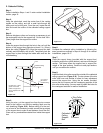
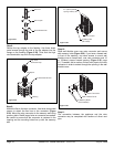
Step 3.
To install the round support box/wall thimble cover in a flat
ceiling, cut a 10 in. (254mm) square hole in the ceiling,
centered on the hole drilled in Step 2. Frame the hole as
shown in Figure 5.13.
Framing
1 - 1/2 in. (38mm) Long
Wood Screws
Ceiling
Joists
Figure 5.13
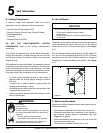
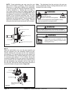
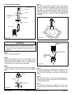
Shingles overlap on
top edge of flashing
CAP AND STORM
COLLAR NOT SHOWN
FOR CLARITY
Figure 5.14
Step 6.
Slip the flashing over the pipe section(s) protruding through
the roof. Secure the base of the flashing to the roof with
roofing nails. Ensure the roofing material overlaps the top
edge of the flashing as shown in Figure 5.14. Verify that
the chimney is the required height above the roof. See roof
pitch table, Figure 4.3, on page 8 of this manual.
specified. Continue to assemble lengths of pipe and elbows
necessary to reach from the ceiling support box/wall thimble
up through the roof line. Galvanized pipe and elbows may
be utilized in the attic, as well as above the roofline. The
galvanized finish is desirable above the roofline, due to its
higher corrosion resistance.