


July 29, 2008
Page 11
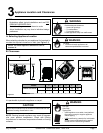
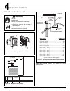
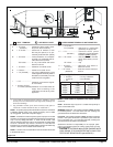
Quadra-Fire · Castile Gas Stove · 7023-111E
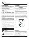
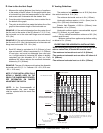
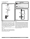
D. How to Use the Vent Graph E. Venting Guidelines
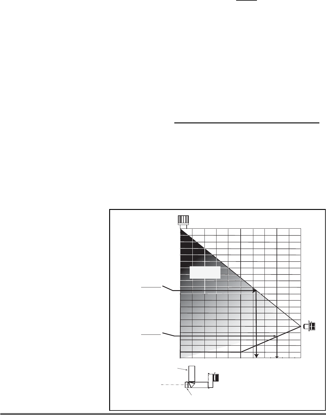
1. Measure the vertical distance from the top of appliance
to the center of the 90° elbow. On the graph below, draw
a horizontal line from that measurement on the vertical
axis across until it intersects with the slanted line.
2. From the point of this intersection, draw a vertical line to
the bottom of the graph.
3. The point at which this line meets the bottom line of the
graph is the maximum length of the horizontal run.
EXAMPLE 1: If the vertical dimension from the center line of
the fl ue vent to the center of the 90° elbow is 7 ft. (2.13 m),
the horizontal run to the outer wall fl ange must not exceed
16 ft. (5m).
EXAMPLE 2: If the vertical dimension from the center line of
the fl ue vent is 21 ft. (6m), the horizontal run to the outer wall
fl ange must not exceed 12 ft. 10 in. (4m).
4. Each 90° elbow is equivalent to 3 ft. (914mm) of vent
pipe and each 45° elbow is equivalent to 1 ft. (305mm)
of vent pipe, and must be subtracted from vent pipe
run. A single vertical to horizontal 90° elbow is already
calculated into the allowable 20 ft. (6m) run. Each
additional 90° elbow reduces the maximum horizontal
distance by 3 ft. (914mm).
EXAMPLE: The use of 3 elbows would reduce the allowable
horizontal run to 9 ft. (3 -1 = 2 elbows x 3 ft. = 6 ft.; 20 ft. max.
- 6 ft. = 14 ft. max.).
NOTE: IF YOUR INSTALLATION FALLS
WITHIN A SHADED AREA ON THE
GRAPH, THE DAMPER MUST BE USED.
SEE INFORMATION ON DAMPER
ADJUSTMENT ON PAGE 34.
NOTES
The maximum horizontal vent run is 20 ft (6m) when
the vertical vent rise is 10 ft. (3m).
The minimum horizontal vent run is 6 in. (152mm).
Horizontal sections require a 1/4 in. (6mm) rise for
every 12 in. (305 mm) of horizontal travel.
Exterior Vent Diameter = 6-5/8 in. (168mm); Inner
Vent Diameter = 4 in. (102mm).
Horizontal sections require noncombustible support
every 3 ft. (914mm), e.g. wall straps.
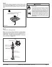
For any vertical termination a minimum of 6 ft. (2m)
vertical must be used.
Minimum vertical from appliance top before adding
an elbow is 2 in. (51mm).
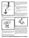
EXCEPTIONS FOR HORIZONTAL INSTALLATIONS:
*When installing this appliance in a rear vent configuration
with no vertical rise, a Snorkel Kit must be used.
*The maximum horizontal vent run is 3 ft. (914mm)
*The maximum horizontal vent run with a 45° elbow is 2
ft. (609mm).
*The minimum horizontal vent run is 6 in. (152mm).
NOTE: In the Commonwealth of
Massachusetts, the word damper
shall be replaced with the words flue
restrictor.
40 ft. Maximum Vertical
HHW2
Example 1
Example 2
No Damper
in this area
Damper position
more OPEN in this
area
2' 4' 6 ' 8' 10' 12' 14' 15' 16' 17' 18' 19' 20'
2'
4'
6'
8'
10'
12
'
14'
16'
18'
20'
22'
24'
26'
28'
30'
32'
34'
35'
36'
37'
38'
39'
40'
Part #SLK-991DA
3 ft. (91 cm) Maximum Horizontal run with no
vertical pipe and with 1/4 in. (6.35 mm) rise per
foot. Must use Snorkel cap.
Damper position
more CLOSED in
this area
6 ft. Min. Vertical
Termination
For rear vent or top of
stove for top vent.
C
L
6 in. Min. starter pipe
C
L
VERTICAL DISTANCE FROM
APPLIANCE TO 90° ELBOW
Figure 5.2