


Page 12
July 29, 2008
Quadra-Fire · Castile Gas Stove · 7023-111E
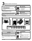
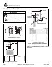
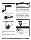
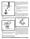
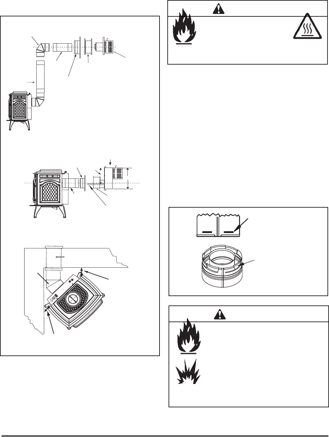
F. Horizontal Termination
45° Elbow
1 in. (25mm) Clearance from appliance
corner to combustible wall
1 in. (25mm)
Clearance from
appliance corner to
combustible wall
Wall Thimble/Heat Shield
Wall Thimble/
Heat Shield
Wall Thimble Cover
Pipe Length
Pipe Length
Termination Cap
Center Line
90° Elbow
Type A - Up and Out Installation
Type B - Straight Out Installation
Type C - 45
° Elbow in Corner Installation
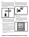
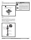
Wall Thimble
Cover
Pipe Length
Snorkel Kit
Wall Strap 14 in.
(356mm) Wide
Minimum 6 in.
(152mm) of pipe
through wall
Wall Thimble or Heat Shield
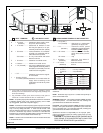
15-5/8 in.
(397mm)
21 in. (533mm)
Center Line
Figure 5.3
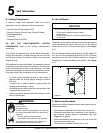
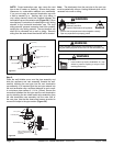
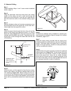
Female Locking Lugs
Male Locking Lugs
Step 1.
Determine the desired location of the appliance. Check to
ensure that wall studs or roof rafters are not in the way when
the venting system is attached. If this is the case, you may
want to adjust the location of the appliance.
Figure 5.4
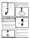
Step 2.
Direct vent pipe is designed with a locking connection. To
connect the venting system to the appliance flue outlet, a
twist-lock adapter is built into the appliance at the factory.
Wall thickness may vary. Remember to include wall
thickness in minimum clearances when figuring venting
lengths for your installation needs.
Note: Female ends of direct vent pipe/elbows are designed
to slide straight onto the male ends of adjacent pipes by
orienting the pipe indentations so they match and slide into
the entry slots on the male ends, see Figure 5.4. Push
the pipe sections completely together, then twist-lock one
section clockwise approximately one-quarter turn, until the
two sections are fully locked. The female locking lugs may
not be visible from the outside. They may be located by
examining the inside of the female ends.
Fire Risk.
Explosion Risk.
Combustion Fume Risk.
Use vent run supports per installation instructions.
Connect vent sections per installation instructions.
• Maintain all clearances to combustibles.
• Do NOT allow vent to sag below connection
point to appliance.
• Maintain specifi ed slope (if required).
WARNING
Improper support may allow vent to sag or separate.
Fire Hazard.
Exhaust Fume Risk.
Impaired Performance of Appliance.
WARNING
• Ensure vent components are locked together correctly.
• Pipe may separate if not properly joined.