


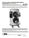
TURBOPOWER 99
WATER HEATER
PV500-12 08/12 7
3. Place the appliance on a level, non-combustible floor. Concrete over wood is not considered non-
combustible.
4. Do not install on carpet or other combustible floor coverings.
5. Installation over a combustible floor: Units installed over a combustible floor MUST be provided with a base
of hollow clay tile or concrete blocks from 8" to 12" thick and extending 24" beyond the sides. Place the blocks
in line so that the holes line up horizontally to provide a clear passage through the blocks. Install 1/2” fireproof
millboard with a 20-gage sheet metal cover over the block base. Center the unit on the base. Also follow this
procedure if electrical conduit runs through the floor, and beneath the appliance. A field-installed base must
meet all local fire and safety code requirements.
4.5 Installation
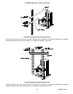
WARNING: Use industry standard safe rigging methods when attempting to lift or move this product.
Failure to follow these instructions could result in property damage, serious injury or death. One common
method includes the use of straps and spreader bars, lifting from the water heater base skid assembly.
1. Check the data decal on the appliance. Be sure the electrical, water, oil, or gas supply is adequate for the
installation.
2. Carefully remove all shipping supports and bracing.
3. Use only non-ferrous water piping and fittings. Do not use galvanized pipe or fittings. Use of ferrous or
galvanized pipe or fittings can cause rust to form.
4. Install shut-off valves and unions on the inlet and outlet water piping for servicing. Use caution when
threading pipe nipples into tank connections to prevent cross threading, or over-tightening. Always use a
back-up wrench on tank nipples when tightening unions, valves, etc.
5. Insulate hot water and return circulation lines. Insulate cold water supply lines if subject to freezing during
shutdown periods. IMPORTANT: Do not use the plumbing connected to the appliance as a ground for
welding or any other purpose.
6. Pipe the drain valve to a suitable open drain.
4.6 Service Clearances
Allow sufficient space to provide adequate clearances on all sides for service and inspection. Recommended
clearance is 24” at the top and front, 18” at left and right sides of the appliance. Optional equipment may increase
the clearance requirements. Allow sufficient space for installing and servicing connections such as water, gas,
vent, combustion air, electrical, pump and other auxiliary equipment.
4.7 Clearances to Combustible Surfaces
The appliance must not be installed on a combustible floor, on carpet, on other combustible floor coverings or on
a non-combustible floor covering combustible material. The minimum clearance to unprotected combustible
material is 6” from the front, top, left and right sides of the burner and flue collector. Combustible materials are
allowed to contact the tank sides and top, however service clearances are recommended.