


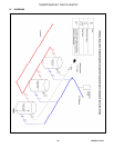
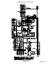
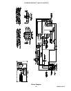

TURBOPOWER 99
WATER HEATER
PV500-12 08/12 18
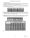
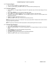
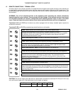
11.8 LED Display Alarm Messages
Alarm messages are displayed in the upper LED readout and alternate with the default display. An alarm LED
ICON is also illuminated. (See TempTrac User Manual PV500-40 for full description.)
ALARM
MESSAGE
CAUSE RESULTS OF ALARM CONDITION
RECOMMENDED
ACTION
“P1” TP1 probe failure
Inlet temperature sensor is not
connected or is reading incorrectly. Call
for heat and burner modulation output
signal will revert to low fire.
Check wiring and sensor
Terminals 14 & 17
“P2” TP2 probe failure
Temperature sensor is not connected
or is reading incorrectly.
Check wiring and sensor
Terminals 15 & 17
If no probe, change
TempTrac setting of P2P
“P3” TP3 probe failure
Temperature sensor is not connected
or is reading incorrectly or flue gas
temperature protection is disabled (if
used).
Check wiring and sensor
Terminals 16 & 17
“HA”
High temperature limit
setpoint exceeded
Buzzer sounds, operation continues Manual reset required
“LA” Low temperature alarm Buzzer sounds, operation continues
HP
Digital input 3 is activated
for one or more of the
following:
Flame failure or any control
component failure, if
equipped with alarm on any
failure option
Unit de-energized after timer delay Manually reset required
LP Digital input 2 is activated Unit de-energized after timer delay Manually reset required
Mn1
Maintenance alarm for
output 1
Buzzer sounds, operation continues Check wiring and sensor
Mn2
Maintenance alarm for
output 2
Buzzer sounds, operation continues Check wiring and sensor
Mn3
Maintenance alarm for
output 3
Buzzer sounds, operation continues Check wiring and sensor
“rtc”
The real time clock has lost
its setting
Energy saving function disabled Reprogram clock