


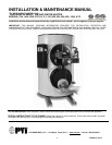
TURBOPOWER 99
WATER HEATER
PV500-12 08/12 2
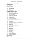
TABLE OF CONTENTS
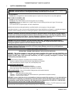
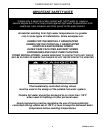
1. Safety Considerations
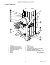
2. Product Descriptions
3. Standard Features and Equipment
3.1 Warranty
4. Water Heater Installation
4.1 Checking Equipment Before You Install
4.2 Codes
4.3 Electrical Requirements
4.4 Location
4.5 Installation
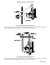
4.6 Service Clearances
4.7 Clearances to Combustible Surfaces
5. Condensate Neutralization & Disposal
6. Combustion and Ventilation Air
7. Vertical and Horizontal Remote Air
7.1 Vertical or Horizontal Remote Air Option
7.2 Remote Air Piping Design
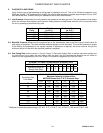
7.3 Maximum Allowed Combustion Air Vent Length (Equivalent Length)
7.4 Remote Air Piping of Multiple Units
8. Venting Products of Combustion
8.1 Vent System Design
8.2 Venting of Multiple Units
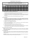
8.3 Maximum Allowed Vent Length (Equivalent Length)
8.4 Vent Construction and Assembly
8.5 Horizontal and Vertical Venting Through a Wall or Roof
9. Gas Supply and Piping
9.1 Inlet Pressure
9.2 Manifold Pressure
9.3 Gas Piping Size
9.4 Appliance Isolation during Gas Supply Piping Pressure Test
9.5 Gas Connection
9.6 Gas Train and Controls Certification
9.7 Gas Control Trains
10. General Information
10.1 Temperature and Pressure Relief Valve(s)
10.2 Upper LED Readout
10.3 High Water Temperature Limit Control
10.4 Cathodic Protection
10.5 Thermal Expansion
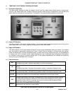
11. TempTrac Electronic Controller Panel
11.1 Principle of Operation
11.2 Lower LED Readout
11.3 Upper LED Readout
11.4 Control Buttons
11.5 To View the Setpoint
11.6 To Change the Setpoint
11.7 To Change Other Parameters
11.8 LED Display Alarm Messages
12. Remote Connections – Terminal Strip
13. Start-up Procedure
14. Periodic Maintenance
15. Diagrams
Warranty forms ship separately with each product.