


TURBOPOWER 99
WATER HEATER
PV500-12 08/12 10
8 VENTING PRODUCTS OF COMBUSTION
The TURBOPOWER
®
99 is designed for operation with a "positive pressure vent system" constructed of locally
obtained 4” or 5" (or larger) schedule 40 or 80 solid PVC or CPVC pipe. Do not use PVC or CPVC pipe with
cell/foam type construction (such as “CellCore”) or other non-solid PVC plastic pipe. Larger solid PVC pipe may
be substituted; however, a PVC increaser to the larger size must be used. Do not insulate the plastic vent pipe.
Stainless steel venting listed by a nationally recognized testing laboratory for category IV positive pressure gas
appliance venting may be used instead of plastic pipe venting.
WARNING: Do not vent this water heater into an existing or traditional gas vent or chimney or combine
the vent with any other appliance. Such venting could result in failure of the venting system and/or
exposure to carbon monoxide which can result in property damage, personal injury or death.
CAUTION: DO NOT use ABS pipe in the venting system. ABS can emit toxic fumes in the event of a building fire.
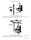
8.1 Vent System Design
These water heater can be vented either vertically, through a ceiling or roof, or horizontally through a wall in any
direction except down. The vent must be installed and supported to slope downward toward the water heater vent
connection with at least ¼ inch drop per linear foot of horizontal vent run, to allow proper drainage of
condensation.
8.2 Venting of Multiple Units
Multiple heaters must not be vented into a common duct or breeching. Each unit must be independently vented
in accordance with the instructions for either horizontal or vertical venting included above.
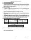
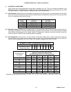
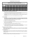
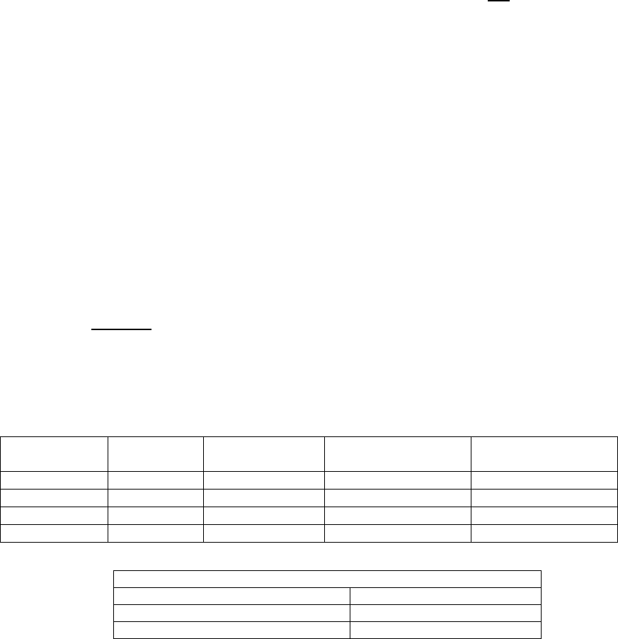
8.3 Maximum Allowed Vent Length (Equivalent Length)
Maximum equivalent length of vent must not exceed the length identified in the table below (consult factory for
longer equivalent lengths):
Water Heater
Prefix
Input, Btu/h
W/Remote Air
Input, Btu/h
100 equivalent feet,
vent diameter:
225 equivalent feet,
vent diameter:
742 500,000 500,000 4” 6”
1485 999,000 950,000 4” 6”
2228 1,500,000 1,500,000 5” 8”
2971 1,950,000 1,850,000 5” 8”
8.4 Vent Construction and Assembly
1. Clean and deburr all solid PVC, or solid CPVC pipe ends and the joint area and trial assemble (dry-fit) the
vent before joining with PVC cement following the cement manufacturer’s instructions for making sound air
and water tight joints.
2. If category IV stainless steel venting listed by a nationally recognized testing laboratory is used, follow the
manufacturer’s instructions and assure all joints provide a water and gas tight assembly.
3. Vent support – The vent system should be supported at intervals no greater than four feet, to prevent sagging
and distortion.
4. Testing for leaks. After the vent is assembled, close the end of the vent. With the gas supply turned off,
energize the combustion blower to apply air pressure to the vent system. Spray each joint and vent
connection with commercially available leak detection liquid to confirm no air is escaping from any point.
Repair any leaks and retest. After testing is complete, REMOVE the temporary vent closure.
5. Attach the PVI vent termination cap supplied with the appliance. This termination is required for proper
operation and no substitution is allowed.
VENT PIPE FITTINGS EQUIVALENT (in feet)
90º Elbow 14 feet
90º Long Radius Elbow 12 feet
45º Elbow 6 feet