


9
WARNING: Test all gas piping
and connections for leaks after install-
ing or servicing. Correct all leaks at
once.
WARNING: Never use an open
flame to check for a leak. Apply a
mixture of liquid soap and water to
all joints. Bubbles forming show a
leak. Correct all leaks immediately.
CAUTION: Make sure external
regulator has been installed be-
tween natural gas supply and heater.
See guidelines under Connecting to
Gas Supply, page 8.
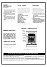
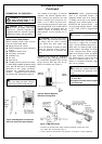
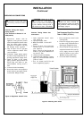
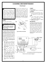
Figure 8 -Equipment Shutoff Valve
Pressure Testing Gas Supply
Piping System
Test Pressures In Excess Of 1/2
PSIG(3.5kPa)
1. Disconnect heater with its
appliance main gas valve (control
valve) and equipment shutoff valve
from gas supply piping system.
Pressures in excess of 1/2 psig
will damage heater regulator.
2. Cap off open end of gas pipe
where equipment shutoff valve
was connected.
3. Pressurize supply piping system
by either using compressed air or
opening propane/LP supply valve.
4. Check all joints of gas supply
piping system. Apply mixture of
liquid soap and water to gas
joints. Bubbles forming show a
leak.
5. Correct all leaks immediately.
6. Reconnect heater and equipment
shutoff valve to gas supply. Check
reconnected fittings for leaks.
Pressure Testing Heater Gas
Connections
1. Open equipment shutoff valve
(see Figure 8).
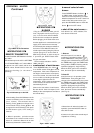
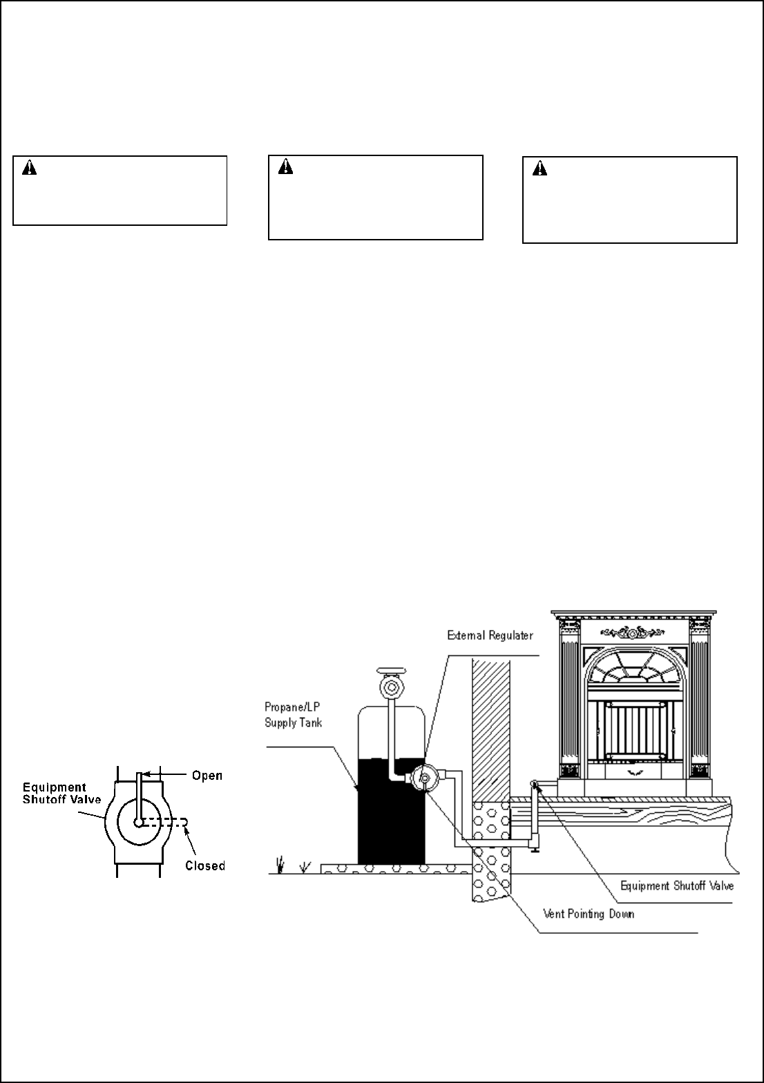
Figure 9 -Checking Gas Joints
INSTALLATION
Continued
CHECKING GAS CONNECTIONS
2. Open gas supply valve.
3. Make sure heater is in the OFF
position.
4. Check all joints from equipment
shutoff valve to control valve
(see Figure 9).
Apply mixture of liquid soap and
water to gas joints. Bubbles form-
ing show a leak.
5. Correct all leaks immediately.
6. Light heater (see Operating Heater,
page 10 ). Check all other internal
joints for leaks.
7. Turn off heater (see To Turn Off
Gas to Appliance, page10 ).
Test Pressures Equal To or Less
Than 1/2 PSIG ( 3.5 kPa )
1. Close equipment shutoff valve
(see Figure 8).
2. Pressurize supply piping system
by either using compressed air or
opening gas supply tank valve.
3. Check all joints from gas meter to
equipment shutoff valve (see Fig-
ure 9). Apply mixture of liquid
soap and water to gas joints.
Bubbles forming show a leak.
4. Correct all leaks immediately.