


8
CONNECTING TO GAS SUPPLY
WARNING: A qualified service
person must connect heater to gas
supply. Follow all local codes.
CAUTION: Never connect heater
directly to the gas supply. This heater
requires an external regulator (not
supplied). lnstall the external regulator
between the heater and gas supply.
INSTALLATION ITEMS NEEDED
Before installing heater, make sure you
have the items listed below.
piping (check local codes)
sealant (resistant to natural or propane/
LP gas)
equipment shutoff valve*
test gauge connection*
sediment trap
see joint
pipe wrench
flexible gas hose (check local codes).
* A CSA design-certified equipment shutoff
valve with 1/8
" NPT tap is an acceptable
alternative to test gauge connection.
Purchase the optional CSA design-
certified equipment shutoff valve from
your dealer. See Accessories, page 16.
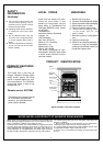
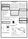
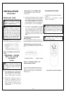
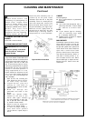
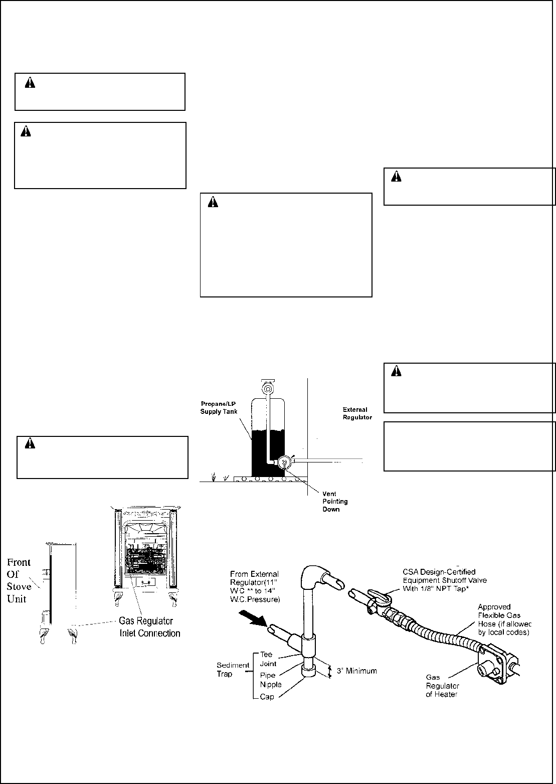
Figure 7 -Gas Connection
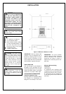
The installer must supply an external
regulator. The external regulator will re-
duce incoming gas pressure. You must
reduce incoming gas pressure to be-
tween 11 to 14
inches. If you do not re-
duce incoming gas pressure, heater regu-
lator damage could occur. lnstall external
regulator with the vent pointing down as
shown in Figure 6. Pointing the vent
down protects it from freezing rain or
sleet.
* Purchase the optional CSA design-certified equipment shutoff valve from
your dealer. See Accessories, page 14.
** 11” W.C. pressure is the minimum inlet pressure for purpose of input adjustment.
INSTALLATION
Continued
WARNING: Never connect heater to
private (non-utility) gas wells. This gas
is commonly known as wellhead gas.
CAUTION: Only use a new black
iron or steel pipe. Internally-tinned cop-
per tubing may be used in certain
areas. Check your local codes. Use
pipe of 1/2
" diameter or greater to allow
proper gas volume to heater. If pipe is
too small, undue loss of pressure will
occur.
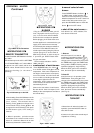
Installation must include an equipment
shutoff valve, union, and plugged 1/8
" NPT
tap. Locate NPT tap within reach for test
gauge hook up. NPT tap must be up-
stream from heater (see Figure 7).
IMPORTANT: Install equipment shutoff
valve in an accessible location. The
equipment shutoff valve is for turning on
or shutting off the gas to the appliance.
Apply pipe joint sealant lightly to male
threads.This will prevent excess seal-
ant from going into pipe. Excess sealant
in pipe could result in clogged heater
valves.
CAUTION: Use pipe joint sealant
that is resistant to liquid petroleum(LP)
gas.
We recommend that you install a sedi-
ment trap in supply line as shown in
Figure 7. Locate sediment trap where it is
within reach for cleaning. Install in piping
system between fuel supply and heater.
Locate sediment trap where trapped
matter is not likely to freeze. A sediment
trap traps moisture and contaminants.
This keeps them from going into heater
controls. If sediment trap is not in-
stalled or is installed incorrectly, heater
may not run properly.
CAUTION: Avoid damage to
regulator. Hold gas regulator with wrench
when connecting into gas piping and/or
fittings.
NG MODELS:
5” to 10.5” W.C.
Gas supplier provides external regulat-
or for natural gas.
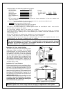
Figure 6- External Regulator
With Vent Pointing Down
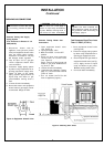
Figure 5-Gas Regulator Location and
Gas Line Access Into Stove Cabinet
Purchase