


Adjustment
59
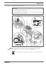
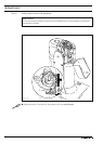
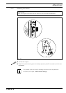
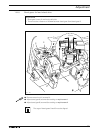
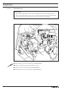
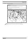
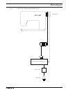
1.07.05 Adjusting the magnets
Requirement
When switch unit 1 is in its left stop position
1. The magnet frame 2 should be positioned at the top stop position and
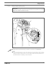
2. The magnet tappet 4 should be completely extended.
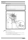
3. When the magnet tappet 4 is extended, there should be no play between the magnet
tappet and lever 5.
● Manually slide switch unit 1 as far as possible to the left (see arrow).
● Adjust magnet frame 2 (screws 3) in accordance with the requirements.
Fig. 1 - 51
3
21
4
3
5