


C3428M-A (1/08) 9
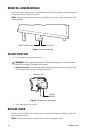
INSTALL BASE
WITHOUT CONDUIT
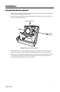
1. Pull the power and video wiring for the camera through the mounting surface and then through the
wiring hole in the mounting plate. Fasten the mounting plate to the mounting surface with #8
stainless steel screws (not supplied) of the appropriate length.
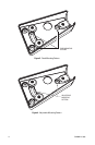
Adjustable mounting pattern only: Adjust the angle of the base before tightening the mounting
hardware.
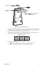
2. Connect the power input wires to the power wires located on the bottom of the IS210 base. Refer to
Table A to connect the power wires:
3. Connect the video cable/wires:
• BNC: Connect the BNC connector from the unit to a mating BNC connector.
• UTP: Connect the blue wire to Video +; connect the gray wire to Video -.
4. Push the power wires and video cable back, through the mounting surface. Align the mounting holes
in the base with the mounting holes of the mounting plate. Attach the base to the mounting plate
with the three 8-32 x 0.375-inch screws and washers previously removed.
WITH CONDUIT
1. Prepare the conduit for the installation.
2. Fasten the mounting plate to the mounting surface with #8 stainless steel screws (not supplied) of
the appropriate length.
Adjustable mounting pattern only: Adjust the angle of the base before tightening the mounting
hardware.
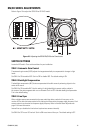
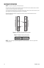
3. Using a blunt tool, push out the wiring plug located in the bottom of the base (refer to Figure 5 on
page 10). Pull the wiring inside the base.
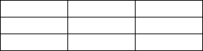
Table A. Power Input
Voltage Red Wire Black Wire
12 VDC + Ground
24 VAC ~ ~