


C3428M-A (1/08) 11
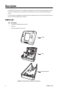
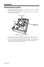
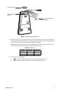
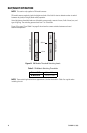
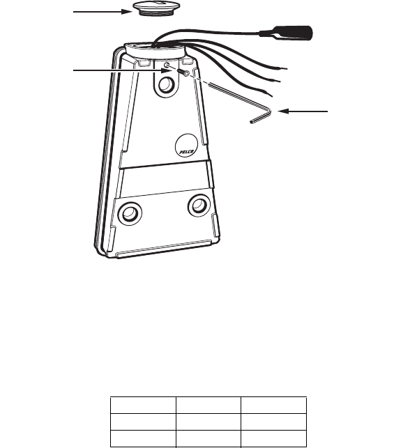
Figure 7. Removing the Conduit Cover
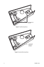
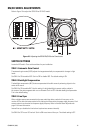
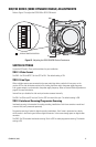
6. Install a 0.75-inch (1.91 cm) conduit connector in the conduit opening. Line up the mounting holes in
the base with the mounting holes of the mounting plate. Attach the base to the mounting plate with
the three 8-32 x 0.375-inch screws and washers previously removed.
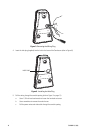
7. Attach the base to the conduit and then connect the power input wires to the power wires of the
IS210 Camclosure. Refer to the following to connect the power wires:
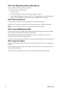
8. Connect the video cable/wires:
• BNC: Connect the BNC connector from the unit to a mating BNC connector.
• UTP: Connect the blue wire to Video +; connect the gray wire to Video -.
Table B. Power Input
Voltage Red Wire Black Wire
12 VDC + Ground
24 VAC ~ ~
1/16-INCH HEX HEAD
WRENCH
HEX HEAD INSET
SCREW
CONDUIT COVER