


18 C1645M-A (9/06)
CONNECTIONS
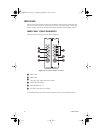
Connections to the FT85041 transmitter and the FR85041 receiver are made on the rear panel of the
modules and consist of the following:
• Power connection
NOTES:
– A 12 VDC or 24 VAC power supply can be used to power the transmitter/receiver when
used as a stand-alone module. A 12 VDC power supply is provided. If a 24 VAC power
supply is used, the power supply must be a Listed Direct Plug-In Power Unit marked as
Class 2 and rated as 24 VAC, 400 mA (minimum output).
– In extreme temperature conditions, it is recommended that an industrial-rated outdoor
power supply such as the Pelco WCS1-4 power supply be used.
• Video input connections (transmitter only)
• Video output connections (receiver only)
• Fiber connection
• Data connection
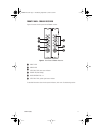
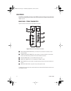
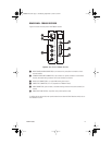
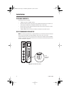
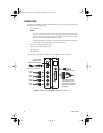
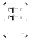
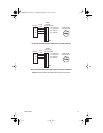
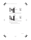
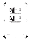
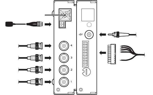
Figure 8 provides an illustration of FT85041 transmitter/FR85041 receiver connections.
Figure 8. FT85041 Transmitter/FR85041 Receiver Connections
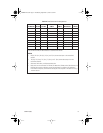
DATA COMMUNICATION
CABLE (REFER TO TABLE B
FOR DATA CONNECTOR
PIN ASSIGNMENTS AND TO
FIGURES 9-14 FOR WIRING
DIAGRAMS)
1
2
3
4
5
6
7
8
GND
POWER CONNECTION
FOR STAND-ALONE MODULE
FIBER OPTIC CABLE
POWER/ALARM
CONNECTION FOR
RACK-MOUNTED MODULE
COAXIAL
CABLE
COAXIAL
CABLE
COAXIAL
CABLE
COAXIAL
CABLE
0
1
2
3
4
5
6
7
8
9
C1645M-A.book Page 18 Wednesday, September 13, 2006 3:07 PM