


12 C1645M-A (9/06)
REAR PANEL
Connections to the FT85041 transmitter and the FR85041 receiver are made to the rear panel of the
module. The following sections provide a view of the rear panel of the FT85041 transmitter and the
FR85041 receiver.
REAR PANEL - FT85041 TRANSMITTER
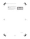
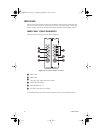
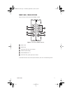
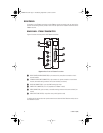
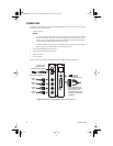
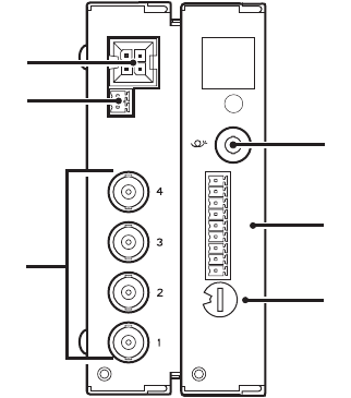
Figure 4 illustrates the rear panel of the FT85041 transmitter.
Figure 4.
Rear Panel of FT85041 Transmitter
For additional information about rear-panel connections and about the Data Selection switch, refer to
the
Installation
section.
ᕡ
RACK POWER/ALARM CONNECTOR, 4-pin connector for power/alarm connection of rack-
mounted module
ᕢ
STAND-ALONE POWER CONNECTOR, 2-pin connector for power connection of stand-alone
module; removable mating connector with screw terminals (not shown)
ᕣ
VIDEO IN CONNECTORS 1-4, 75-ohm BNC analog video input
ᕤ
FIBER OPTIC CONNECTOR, ST or FC (dependent on FT85041 model)
ᕥ
DATA CONNECTOR, 9-pin connector; removable mating connector with screw terminals (not
shown)
ᕦ
DATA SELECTION SWITCH, 10-position rotary switch (positions 0-9)
ᕣ
1
2
3
4
5
6
7
8
GND
ᕦ
ᕤ
ᕡ
ᕢ
ᕥ
0
1
2
3
4
5
6
7
8
9
C1645M-A.book Page 12 Wednesday, September 13, 2006 3:07 PM