


Pelco Manual C459M-E (1/96) 3
4.0 INSTALLATION
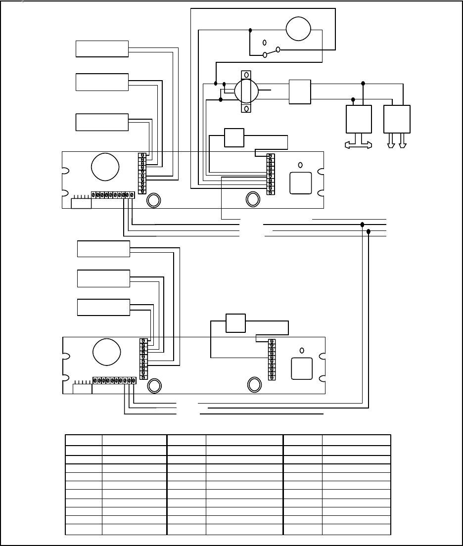
4.1 BLOWER AND HEATER ELECTRICAL CONNECTION (IF APPLICABLE)
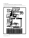
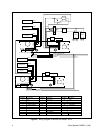
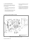
The heater and blower assemblies are factory pre-wired for power input and only require connection of power to the
terminal block. Refer to Figure 2, 3 or 4 for the proper connections.
Figure 2. Wiring Diagram for Blower and Heater, 120V
11
12
13
14
15
16
17
18
19
20
LENS
5 34 21
1 2 5 6 734
23
21
22
24
25
26
27
28
29
30
11
12
13
14
15
16
17
18
19
20
LENS
5 34 21
12 56734
FAN
PCB9000255A
PCB9000255A
WHITE
WHITE
WHITE
WHITE
WHITE
WHITE
WHITE
WHITE
WHITE
WHITE
WHITE
WHITE
WHITE
MOTOR
80W @ 120VAC
80W @ 120VAC
37.5W DEFROSTER
120 VAC
FAN
SOLENOID PUMP
DIODE
BRIDGE
INPUT
80W @ 120VAC
80W @ 120VAC
37.5W DEFROSTER
120 VAC
AC HIGH
AC NEUTRAL
GROUND
VAC INPUT WIRING DIAGRAM
AC
AC
+
-
1
2
4
5 6
8
10
S1
BLACKCOM
N.O
.
N.C.
VIOLET
BLUE
1098
1098
1
2
3
4
5
6
7
8
9
10
11
12
13
14
15
16
17
18
19
20
21
22
23
24
25
26
27
28
29
30
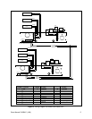
Number
Function
Iris
Zoom
Focus
Lens Common
Manual Iris
Wiper On (Control)
Camera On
AC Input High
AC Input Neutral
Ground
Number Function Number Function
Fan
Not Used
Not Used
Not Used
Fan
Wiper Trigger
Wiper Neutral
Connected to #6
Wiper High
Camera
Defroster
Defroster
Heater #2
Heater #2
Not Used
Heater #1
Heater #1
AC High
AC Neutral
Ground
21
22
23
24
25
26
27
28
29
30
WASHER TRIGGER INPUT LINE
AC HIGH
AC NEUTRAL
GROUND