


8 Pelco Manual C459M-E (1/96)
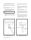
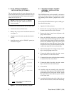
4.4 SUN SHROUD ASSEMBLY
INSTALLATION (OPTIONAL)
The sun shroud provides air space between the sun
shroud and the enclosure to protect from direct rays of
the sun and reduces the internal temperature approxi-
mately 10-15°F (6°-10°C).
NOTE: Use the six (6) 10-32 x .375 Phillips
head screws and nylon washers from the en-
closure assembly.
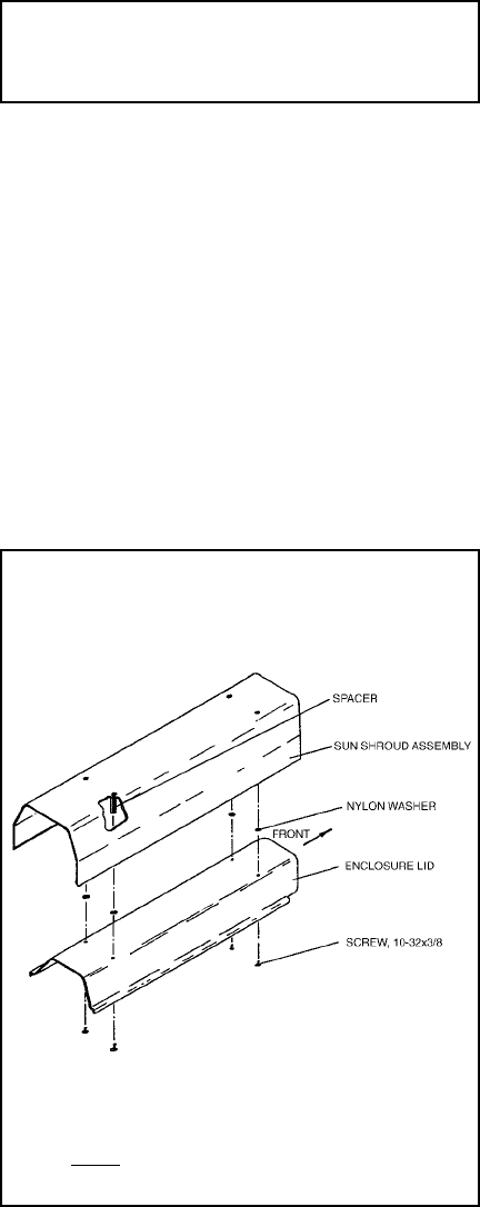
To install the sun shroud, perform the following steps:
1. Unlatch the enclosure lid and raise.
2. Remove the six (6) screws from the enclosure lid
(see Figure 7).
3. Align the screw holes in the sun shroud and enclo-
sure lid.
4. Install the screws (and six SPA8467 spacers) as
illustrated in Figure 7.
4.5 WW6500 WINDOW WASHER
ASSEMBLY INSTALLATION
(OPTIONAL)
The WW6500 window washer assembly is designed to
allow the viewing window to be cleaned by a wiper
and cleaning solvent which is pumped from a reser-
voir.
To install the WW6500 window wiper assembly, per-
form the following steps.
1. Open the lid of the enclosure.
2. Remove the two large hole plugs located in the
bottom towards the front of the enclosure.
3. Remove the four (4) nuts/screws adjacent to the
plugs removed above.
4. Place the WW6500 wiper box up to the front/
bottom of the enclosure and align the four mount-
ing holes of the above item with the four mounting
holes in the WW6500 and pull the control wires
through the holes opened by item 2 above. Then,
using the four screws provided with the WW6500,
connect the wiper box to the enclosure body.
5. Hard wire the purple wire exiting the wiper assem-
bly to the wiper pump control wire.
6. Connect the white wire exiting the wiper assem-
bly to terminal 27 of the circuit board.
7. Connect the blue wire exiting the wiper assembly
to terminal 28 of the circuit board.
8. Connect the black wire exiting the wiper assem-
bly to terminal 29 of the circuit board.
9. Close the lid.
10. Attach the wiper arm assembly to the wiper shaft
on the front of the wiper box. The blade should be
positioned to the left side of the window. Attach
the wiper follower arm to the hex spacer to the left
of the wiper shaft.
11. Attach the fluid bottle to the back of the air box on
the rear of the enclosure. Connect the fluid tubing.
Figure 7. Sun Shroud Assembly Diagram
NOTE: ONLY FOUR OF SIX SCREWS ARE
ILLUSTRATED