


C3407M-D (1/07) 7
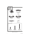
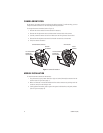
Cover and Back Box Installation
The ICS150-CW Series Camclosure integrated camera system mounts only into a wall or ceiling.
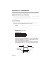
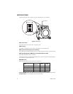
UNSHIELDED TWISTED PAIR (UTP) VIDEO
The ICS150-CW Series offers support for unshielded twisted pair (UTP). The UTP video output signal
is 1 Vp-p differential into a 100-ohm load. The unit uses active UTP.
At a minimum, UTP requires Cat5, 100-ohm twisted pair cable. The maximum UTP wiring distance is
3,000 ft (914 m).
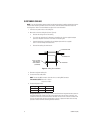
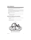
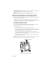
FIXED CEILING/WALL
NOTE:
You should install the camera module into the back box before installing the back box into the
surface. When installing the back box into the surface, rotate the camera module to access the
mounting holes. Refer to
Camera Module
on page 10 for more information.
1. Cut a hole 3.5 inches (9 cm) in diameter in the ceiling/wall. Use the supplied adapter plate as
a template.
2. Pull video and power wires through the ceiling/wall.
3. Connect the video cable/wires:
BNC:
Connect the BNC connector from the unit to a mating BNC connector.
Twisted Pair (UTP):
Blue wire = Video +
Gray wire = Video -
4. Connect the power wires.
AC operation only:
If you are wiring more than one Camclosure integrated camera system to
the same transformer, connect one side of the transformer to the red wire on all units, and
connect the other side of the transformer to the black wire on all units. Failure to connect all of
the units the same way will cause the cameras to be out of phase with each other and may
produce a vertical roll when switching between cameras.
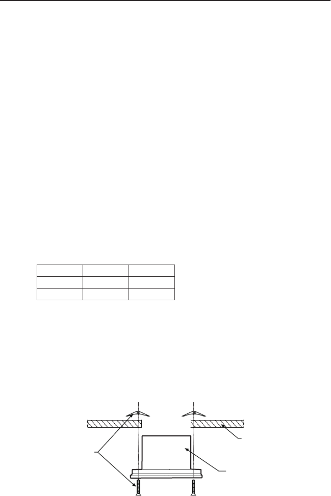
5. For a non-concrete ceiling/wall, use 6-32 toggle bolts to attach the surface mount ring and
back box to the mounting surface. For a concrete ceiling/wall, use 8-32 mounting hardware.
Mounting hardware is not supplied.
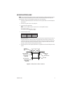
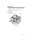
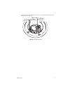
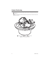
Figure 2.
Ceiling/Wall Installation
Voltage Red Wire Black Wire
12 VDC + Ground
24 VAC ~ ~
MOUNTING
HARDWARE
(NOT SUPPLIED)
WALL OR
CEILING
BACK BOX