


Thermific
®
Gas-Fired Boiler Installation
Page 6
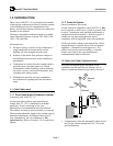
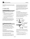
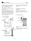
3.3.3 Exhaust Vent Connection at the Boiler
6' Min.
Pitch toward boiler
1/4" per foot min.
3" Min.
Trap Loop
To sewe r t ra p
or condensate pump.
Boot Tee/
135 Tee
o
Condensate Drain
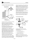
At the outlet of the boiler, an adjustable or fixed length
(minimum 2 feet for clearance from inlet duct;
maximum 3 feet for proper lift) section may be
utilized. This section must be secured to the outlet
collar by a minimum of 4 sheet metal screws spaced at
approximately 90 degree intervals.
Even though the unit is classified as a Category I
boiler (Non-pressurized-non condensing), there are
certain abnormal conditions which may cause
condensation in the flue vent. Therefore, it is
recommended that a tee cover with a drain be provided
at the bottom of the boot tee/135º tee. For proper
disposal of the condensate, corrosion resistant tubing
or plastic tubing should be connected to the drain
nipple. Before connecting the tubing to the tee cover
nipple, the trap loop must be primed by pouring a
small quantity of water into the drain line. The
condensate drain line can be routed to a sewer drain
trap or pump. Consult the vent manufacturer's
instructions for proper installation of drain line.
In transitioning from horizontal to vertical, a double
wall boot tee/135º tee must be installed (not a standard
tee). If the flue gas exhaust is to be routed through the
sidewall, a minimum vertical rise of 6 feet is required
from the outlet of the boot tee/ 135º tee to the inlet of
the elbow. In addition, for sidewall venting, it is
very
important
to provide a downward pitch of at least 1/4
inch per foot of run from the termination at the wall
toward the boiler for proper drainage of the condensate
and for buoyancy assist of the flue gas. Furthermore,
do not
locate sidewall terminations over area of
pedestrian or vehicular traffic due to potential
condensate drippage and ice build-up. See Section 3.4
Clearances for more information.
When joining the double wall tubing and fittings, it is
important to orient the male end of the section toward
the boiler. The female end is positioned away from
the boiler towards the vent terminal. Follow the vent
manufacturer's instructions for proper installation.
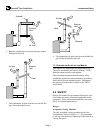
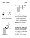
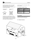
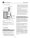
3.3.4 Flue Gas Termination
12" Min.
Recommended
termination
(refer to text).
Sealant
Centering
Support
Plate
Outside Plate
Cover Plate
Fastener
Sealant
The exhaust vent termination must be a P-K
recommended device. There are four approved
sidewall terminations:
90º elbow pointing down, or
Two 45º elbows pointing down, or
45º elbow pointing down, or
Standard tee pointing up/down.
Important:
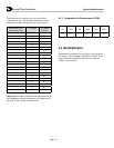
The equivalent length of the chosen
termination must be included in the calculation of the
maximum allowable equivalent length. See Section
3.4.5 for equivalent lengths.