


Thermific
®
Gas-Fired Boiler Installation/Operation
Page 9
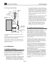
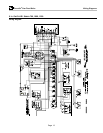
3.4.3.2 Series 1500, 1700, 2000
Air Inlet
Exhaust
Vent
Round
Damper
90 Elbow
o
Transition
Duct
27" Min.
*
31"
*
24"
44" Min.
*
To Drain
Boot Tee/
135 Tee
o
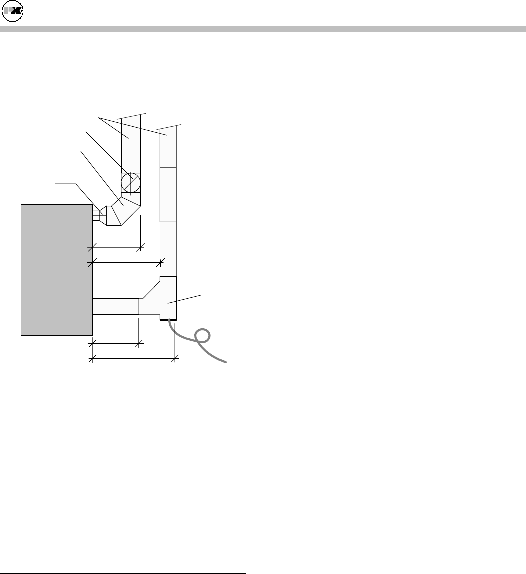
* Dimension shown above is based on 12" round
ductwork.
A minimum of 44 inches is required behind the boiler
to fit the inlet and exhaust connections.
The figure above suggests a duct arrangement using
standard duct pieces that will maintain this minimum
clearance of 44 inches.
4.0 OPERATION
4.1 S
EQUENCE OF
O
PERATION
This sequence applies if the optional inlet damper
assembly and auxiliary control panel are used. If not
the standard Thermific® control sequence applies.
(Replaces step #6 of the Sequence of Operation in the
Installation and Owner's Manual. "TBIG.")
6. The programmer first energizes Terminal 4 which
supplies power to the airflow switch and initiates
the adjustable 120 sec. timer on the time delay
relay. Terminal 4 also supplies power through the
normally closed contacts on the time delay relay
and energizes the coil on the relay in the Auxiliary
Control Panel. The relay will in turn energize the
damper actuator to open the damper. When the
damper is in the full open position, the limit switch
will close and supply power to the contactor for
the blower motor.
During this time (about 20 seconds), the air switch
will indicate low air flow with the "LowAir"
indicator. This indicator will remain on until
sufficient air flow is sensed. If the air flow switch
is not closed in 120 seconds, the time delay relay
will open its normally closed contacts. This will
turn off the blower motor and close the inlet
damper. The "Low Air" indicator will remain
illuminated and the boiler will not operate.
4.2 C
OMBUSTION
O
PERATING
C
ONDITIONS
The combustion air characteristic of the burner in this
boiler is factory set at a condition of utilizing
approximately 50% excess air at room temperature
(70ºF). Therefore, when taking combustion air from
the outdoors in a direct vent system, adjustment of the
combustion air damper linkage should not be made
until the carbon dioxide or oxygen reading is referred
to this condition.
The density of cold outdoor air will be greater than
warm air taken from inside the building. Thus, the
combustion air blower with outdoor air will deliver a
higher air density flow to the burner.
A boiler can be subjected to varying combustion air
temperatures. You must put some thought into the
air/fuel adjustments to prevent hard start and/or light
off rumbling problems. Due to a wide range of
operating conditions, Patterson-Kelley developed a
guide for different conditions.
P-K recommends that the service technician observe
the combustion air temperature range.
Identify the
temperature operating conditions of your boiler.
The operational range setting for O
2
is 6.0% to 8.0%.
Insert your 100º F operating temperature range in the
chart below. Start with the Minimum Temperature at
the top of the chart; insert temperatures using 5º F
increments.