


Thermific
®
Gas-Fired Boiler Installation
Page 5
with the application of heat. Refer to the
manufacturer's instructions. Wrap the joint with
aluminum tape which is backed with an adhesive on
the contact side.
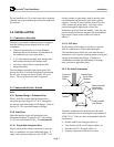
3.2.5 Inlet Damper and Auxiliary Control
Panel (optional)
Note:
The inlet damper assembly and control panel will
prevent the flow of cold air through the boiler during
the off cycle and prevent freeze up. These two items
are
optional
in all installations.
Refer to Section 4.1 for a description of the control
sequence applicable to the inlet damper.
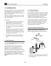
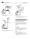
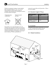
The damper must be field installed into a section of
horizontal or vertical inlet ductwork. Orient the
damper such that the arrow points towards the boiler.
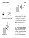
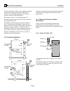
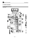
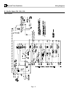
3.2.5.1 Field Wiring to Auxiliary Control Panel
The auxiliary control panel controls the inlet damper
(if used). The auxiliary control panel does not have to
be mounted on or near the boiler; it can be remotely
mounted.
Use 16GA MTW Wire for all field wiring. See
Section 6 for the logic and wiring diagrams of this
auxiliary control panel and the sealed combustion
boilers.
There are five (5) field run wires between the boiler
and its auxiliary control panel; three (3) for main
power supply and two (2) wires for boiler
interconnect.
1. The main power supply (G/H/N) must come from
the same boiler that the damper is connected to.
2. Remove the blue jumper wire in the terminal block
on the boiler when wiring.
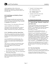
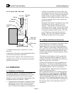
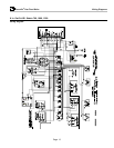
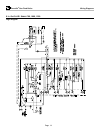
There are also five (5) field run wires between the
auxiliary control panel and the inlet damper assembly;
three (3) to the damper actuator and two (2) to the
limit switch.
1. Terminals for the damper actuator:
DO = Damper Open (CW)
DC = Damper Closed (CCW)
DN = Neutral/Common
2. Terminals for the limit (end) switch
SI = N.O. (Normally Open)
S2 = Common
3.3 E
XHAUST
V
ENTING
S
YSTEM
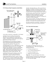
3.3.1 System Design - Materials, Length, Size,
and Construction
The flue gas outlet (exhaust vent) must be designed to
comply with UL 1738 and ULC-636. (Refer to
Section 1.1.2 for situations where alternate compliance
may be permitted.) The exhaust vent can be run
horizontally or vertically.
The vent must be sized according to the vent
manufacture's recommendations. Consult the vent
supplier for correct sizing and structural support
requirements. Vent diameter is dictated by the length
and height of horizontal and vertical portions of the
vent installation and materials of construction. Design
calculations should be based on a negative 0.03 W.C.
with a stack temperature of 325º F (gross) and a CO
2
level of 7.6%; (these values are to be used for vent
sizing calculations.) The
maximum
allowable length
of the vent duct, including the boot tee/135º tee (not a
standard tee) and the termination is 100 equivalent
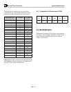
feet. See Section 3.4.5 for the equivalent length of the
fittings.
3.3.2 Flue Gas Outlet Duct
The installation must follow the vent manufacturer's
instructions in all respects including proper joining and
sealing of the tubing and fittings, clearances to
combustible materials and installation of firestops.