


Thermific
®
Gas-Fired Boiler Installation
Page 3
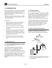
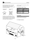
Do not manifold two (2) or more units into a common
sidewall vent system without provisions for additional
forced draft.
3.0 INSTALLATION
3.1 C
OMPONENTS
P
ROVIDED
The direct vent/sealed combustion option is shipped
with the following items shipped loose for field
installation:
Custom 6 inch diameter to 12 inch diameter
transition duct with extension, for attachment to
the combustion air inlet on the boiler.
A 12" inlet damper assembly with actuator and
limit switch mounted to the damper shaft.
Auxiliary Control Panel to operate the inlet
damper assembly.
The inlet damper assembly and control panel will
prevent the flow of cold air through the boiler during
the off cycle and prevent freeze up and "off cycle"
losses. The use of these two items is optional.
3.2 C
OMBUSTION
A
IR
I
NLET
S
YSTEM
Note:
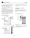
3.2.1 System Design - Pressure Drop
The air inlet duct system shall be designed for a
maximum pressure drop of 0.05" W.C. taking into
account the equivalent length of all fittings. Refer to
Section 3.4.5 for equivalent length of fittings.
3.2.2 Inlet Duct
Materials shall be single wall galvanized duct
(minimum thickness 26 gauge) or PVC duct tubing
(0.187 inch wall thickness) only.
No substitutions.
3.2.2.1 Single Wall Galvanized Duct
Proper sealing of the tubing is necessary to prevent
flow of combustion air from conditioned space. If
single wall galvanized tubing is used, GE RTV 102
silicone sealant, or equivalent, must be used on each
circumferential and horizontal joint before joining
together. At least 24 hours must be allowed for cure
of this sealant and proper bond. Cure time can be
reduced through the application of heat (See
instructions provided with the sealant). After the cure
period, each joint must be wrapped with an aluminum
tape which is faced on the contact side with an
adhesive.
3.2.2.2 PVC Duct
Proper sealing of the tubing is necessary to prevent
flow of combustion air from conditioned space.
The installation must follow the vent manufacturer's
instructions in all respects including proper joining and
sealing of the tubing and fittings. Clearances to
combustible materials and installation of firestops
must conform to applicable codes.
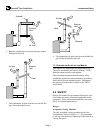
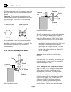
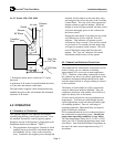
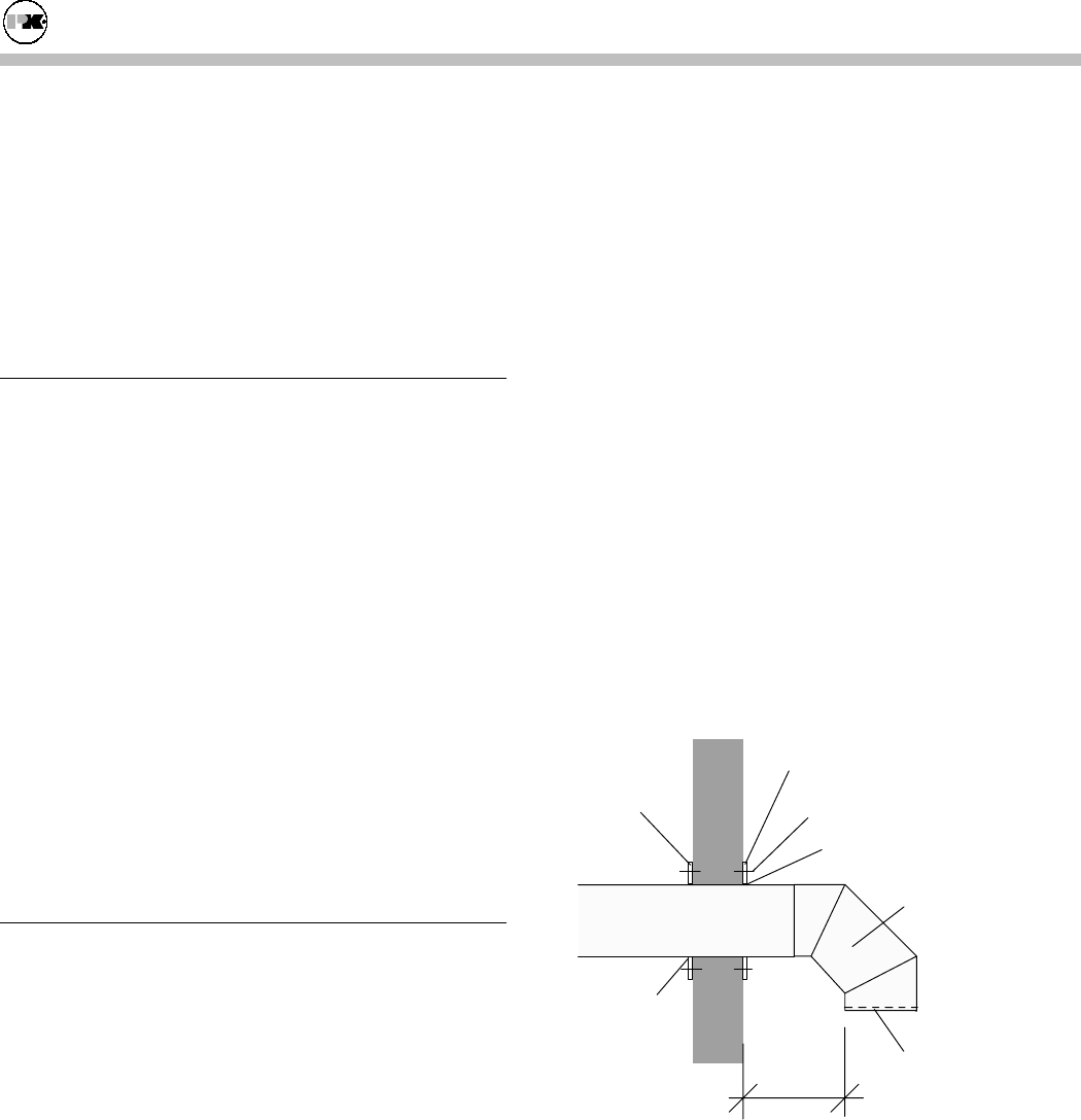
3.2.3 Air Inlet Termination
12" Min.
Recommended
Termination
(refer to text).
Sealant
Centering
Support
Plate
Outside Plate
Cover Plate
Fastener
Sealant
Field Provided
Inlet Screen
The boiler combustion air inlet duct must be fitted
with a termination device meeting the requirements of
ANSI Z21.13. There are four recommended sidewall
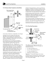
terminations:
•
Double wall B vent 90 degree elbow, or
•
Two double wall B vent 45 degree elbows, or
•
Schedule 40 PVC 90 degree elbow, or
•
Properly engineered intake louver screen.