


Thermific
®
Gas-Fired Boiler Installation
Page 4
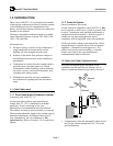
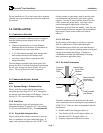
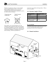
Whichever material is used, the termination must point
down and must be backed by a metal plate secured to
the wall.
Important:
The chosen inlet termination must be
included in the calculation of the maximum allowable
equivalent length. See Section 3.4.5 for equivalent
lengths.
Correct rain cap,
unrestricted.
Typical incorrect
rain cap.
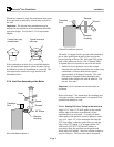
If the combustion air inlet duct is routed through the
roof, the termination must be either the same type as
described for a sidewall installation or a rain cap. The
rain cap must be unrestrictive type similar to the
illustration below.
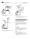
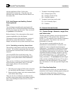
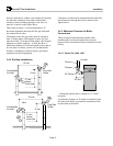
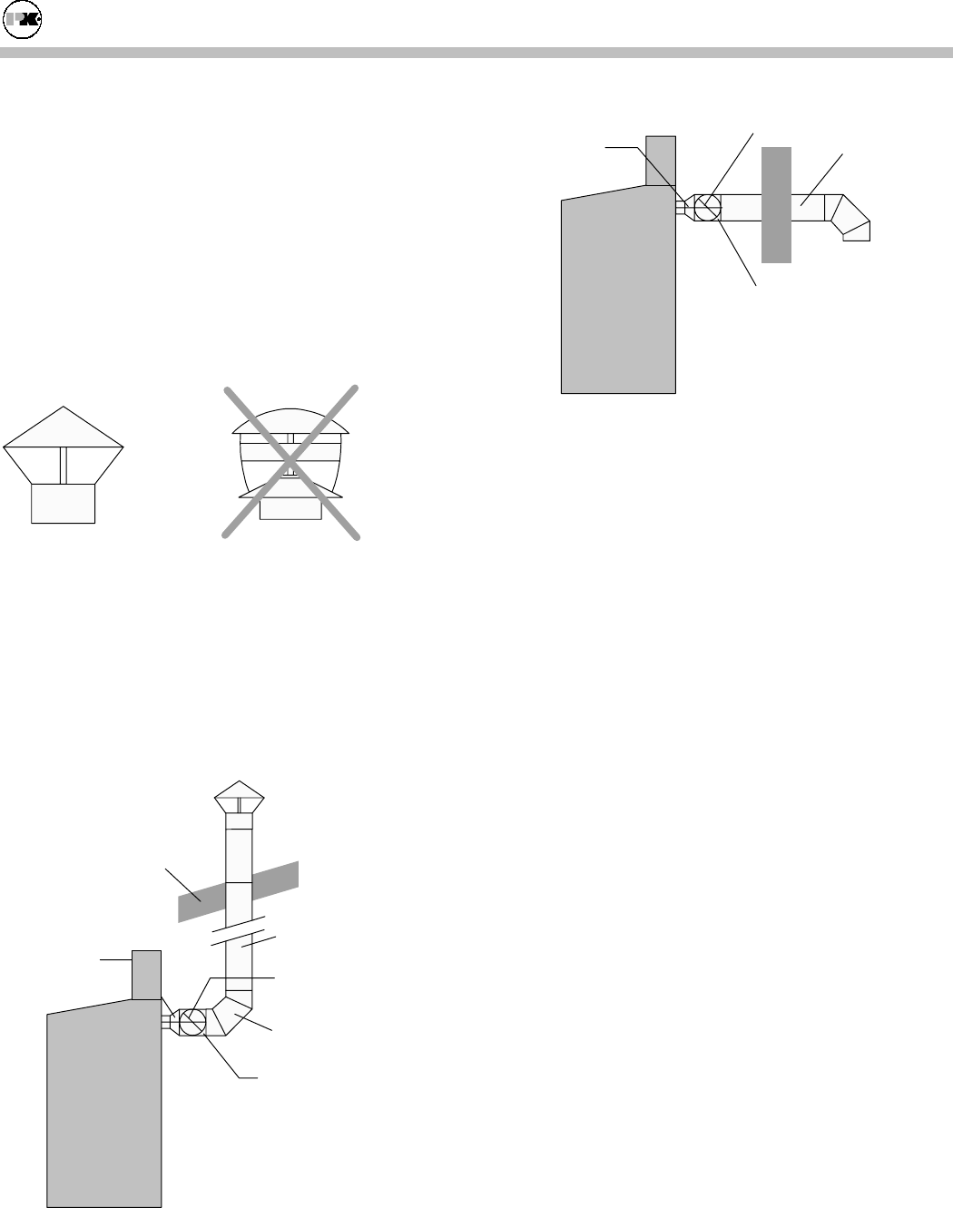
3.2.4 Inlet Duct Assembly at the Boiler
Round
Damper
90 Elbow
o
Transition
Duct
Damper
Housing
Roof
(Roof installation shown.)
Round
Damper
Transition
Duct
Damper
Housing
(Sidewall installation shown.)
The boiler is equipped with a special collar attached to
the air inlet opening on the back of the unit (at the
blower housing on Series 700, 1000, and 1200; at the
back of the cabinet on Series 1500, 1700 and 2000.).
A separate box of accessories is sent with the boiler.
1. Attach the 6 inch diameter end of the custom
transition duct and the extension to the collar using
a minimum of 4 sheet metal screws spaced
approximately at 90 degree intervals. This joint
must then be wrapped with an aluminum tape
backed on the contact side with an adhesive. Do
not use "duct tape."
Important:
do not insulate the transition duct or
extension.
Refer to Section 3.2 for instructions for installing and
wiring the auxiliary control panel; it is required if the
optional inlet damper is used.
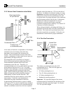
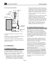
3.2.4.1 Sealing PVC Duct Tubing to the Inlet Duct
Apply a 3/4" wide x 1/8" thick gasket to the outside
surface edge of the entire circumference of the
transition duct (or extension). A closed cell foam
rubber gasket with pressure sensitive adhesive works
very well. Insert 3/4" of the transition duct into the
PVC duct tubing so that the gasket lines up with the
edge of the PVC tubing. Lay an approximate 3/8"
wide bead of GE RTV-102 silicone sealant, or
equivalent, along the gap between the gasket and
inside wall of the tubing. Allow the silicone sealant to
cure for 24 hours. The cure time can be shortened