14
REPLACEMENT OF MAIN PARTS
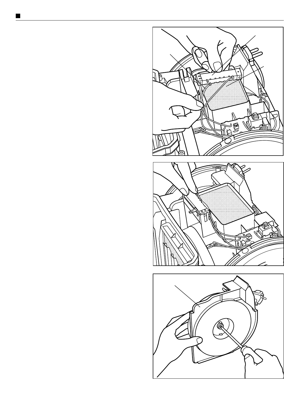
Fig. 15
(3) Sliding Potentiometer
1. Remove upper body as explained previously in paragraph
(1) “Motor”, points 1-3.
2. Take out the sliding potentiometer from its support and
remove lead wires (blue and grey) from the potentiometer
tabs. (Fig. 15)
NOTE: Observe the correct position of the lead wires
before installing the new one.
Sliding potentiometer
Grey lead wire
Blue
lead wire
Fig. 16
3. Replace the potentiometer with a new one and connect the
lead wires (blue and grey) to the potentiometer tabs.
4. Reinstall the potentiometer in its support and reassemble
the remaining parts in the reverse order. (Fig. 16)
• CORD REEL UNIT / POWER CORD
(1) Cord reel unit.
1. Remove upper body and cord reel ass’y as explained
previously in paragraph (1) “Motor”, points 1-4.
2. Before removing the screw that fix the cord reel unit and
cord reel support unwind the power cord to release the cord
reel spring efficiency. Them remove the screw .(Fig. 17)
Fig. 17
Cord reel ass’y


