12
REPLACEMENT OF MAIN PARTS
Fig. 11
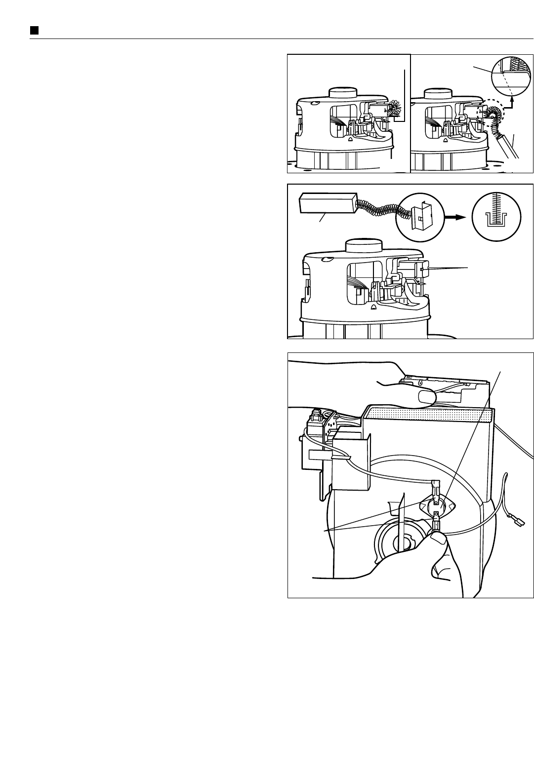
(2) Carbon brushes
NOTE: The two carbon brushes should be replaced at
the same time.
1. Take out motor unit and remove motor cover A and B as
explained previously in paragraph (1) “Motor”, points 1-6.
2. Disconnect yellow and black lead wires (provided with
quick-connect terminals) from the carbon brush holder tabs.
3. Bend the metal end of the carbon brush holder and take out
the carbon brush. (Fig. 8)
4. Cut off the metal end of the carbon brush. (Fig. 9)
Fig. 10
Fig. 9
Fig. 8
Cut metal end
Carbon
brush
Carbon brush
Metal end
holes
5. Insert the new carbon brush into the brush holder and push
the carbon brush until the protruded pins of the brush holder
fix into the holes of the metal end. (Fig. 10)
6. Connect yellow and black lead wires to the carbon brush
holder tabs and reassemble motor unit.
7. Place motor unit and cord reel ass’y into the lower body.
8. Connect the lead wires according to the schematic diagram
and reassemble the remaining parts in the reverse order.
Metal end
• THERMAL CUT-OUT
1. Take out cord reel ass’y and motor unit as explained
previously in paragraph (1) Motor, points 1-4.
2. Take out thermal cut-out from its fastening points and
disconnect lead wires (provided with quick-connect
terminal) from the thermal cut-out tabs. (Fig.11)
3. Replace the thermal cut-out with a new one and connect the
lead wires to the tabs. Then re-install it.
4. Place motor unit and cord reel ass’y into the lower body.
6. Connect the lead wires according to the schematic diagram
and reassemble the remaining parts in the reverse order.
Termal cut-out
Thermal
cut-out
tabs


