


234
EX-10
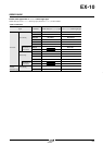
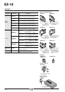
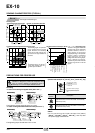
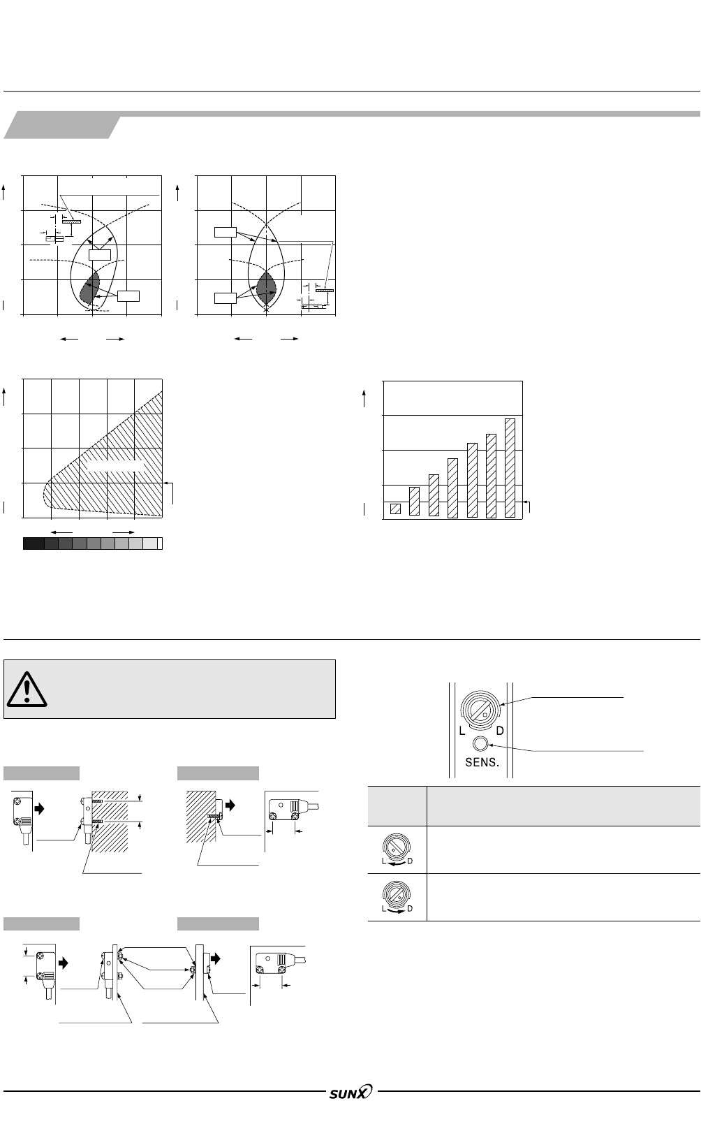
Operation mode switch
L: Light-ON
D: Dark-ON
Lights up when the output is
ON.
Operation indicator (Orange)
Switch
position
Description
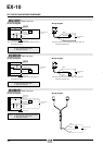
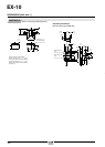
• Vertical (up and down) direction
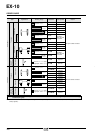
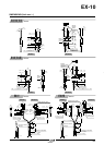
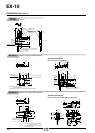
SENSING CHARACTERISTICS (TYPICAL)
Convergent reflective type
Sensing fields
•
Horizontal (left and right) direction
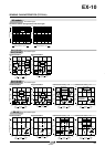
Correlation between lightness and sensing range
Correlation between material (50ן50 mm 1.969ן1.969 in) and sensing range
5
0.197
10
0.394
05
0.197
10
0.394
0
10
0.394
20
0.787
30
1.181
40
1.575
White
N4
7 mm
0.276 in
#
L
Setting distance L (mm in)
Left
Right
Center
Operating point ?(mm in)
50ן50 mm 1.969ן1.969 in
Non-glossy paper
0
10
0.394
20
0.787
30
1.181
40
1.575
N2 N4 N6 N8
Lightness LightDark
N2N1 N3 N4 N5 N6 N7 N8 N9
Sensing range L (mm in)
Sensing region
Distance to
convergent point
0
20
0.787
10
0.394
40
1.575
60
2.362
80
3.150
Sensing range L (mm in)
Black circuit board
Black rubber sheet
IC tray (Black)
Glass epoxy printed circuit board
(Green masked surface)
Ceramic circuit board
White non-glossy paper
Stainless steel plate
Aluminum plate
(Hair line)
Aluminum-evaporated mirror
Distance to convergent point
EX-14Ⅺ
The sensing region is represent-
ed by oblique lines in the left
figure. However, the sensitivity
should be set with enough mar-
gin because of slight variation in
products.
Lightness shown on the left
may differ slightly from the
actual object condition.
The bars in the graph indicate the
sensing range for the respective
material. However, there is a
slight variation in the sensing
range depending on the product.
Further, if there is a reflective
object (conveyor, etc.) in the
background of the sensing object,
since it affects the sensing,
separate it by more than twice the
sensing range shown in the left
graph.
5
0.197
10
0.394
05
0.197
10
0.394
0
10
0.394
20
0.787
30
1.181
40
1.575
White
N4
#
7.75
mm
0.305 in
L
Setting distance L (mm in)
Down
Up
Center
Operating point ?(mm in)
50ן50 mm
1.969ן1.969 in
Non-glossy paper
()
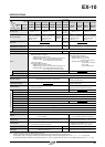
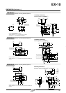
The tightening torque should be 0.2 N⅐m or less.
Dark-ON mode is set when the switch is turned fully
counterclockwise (D side).
The tightening torque should be 0.2 N⅐m or less.
•
In case of using attached screws and nuts (Unit: mm in)
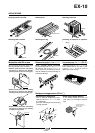
PRECAUTIONS FOR PROPER USE
This product is not a safety sensor. Its use is not
intended or designed to protect life and prevent body
injury or property damage from dangerous parts of
machinery. It is a normal object detection sensor.
Mounting
• In case of mounting on tapped holes (Unit: mm in)
Side sensing
Front sensing
Side sensing Front sensing
M2ן0.4 0.016 hole
tapped, 6 0.157 deep
Attached
screw
[M2 (length 10 0.394)]
11
0.433
Sensing
direction
Sensing
direction
M2ן0.4 0.016 hole
tapped, 7 0.276 deep
[M2 (length 8 0.315)]
Attached
screw
11
0.433
Thickness of
mounting plate: 2 0.079 or less
Attached
screw
[M2 (length 10 0.394)]
Thickness of
mounting plate: 2.5 0.098 or less
Spring
washers
Nuts
Flat washers
[M2 (length 8 0.315)]
Attached
screw
Sensing
direction
Sensing
direction
11
0.433
11
0.433
Operation mode switch (EX-15Ⅺ, EX-15EⅪ, EX-17Ⅺ and EX-17EⅪ only)
Light-ON mode is set when the switch is turned fully
clockwise (L side).
Others
• Do not use during the initial transient time (50ms)
(EX-15Ⅺ, EX-15EⅪ, EX-17Ⅺ, EX-17EⅪ: 100 ms) after
the power supply is switched on.
08/2005